background image

General information

About this manual

This operating and installation manual enables oper-

ating or service personnel to correctly install the TROX

product described below and to use it safely and effi-

ciently.

This operating and installation manual is intended for

use by fitting and installation companies, in-house tech-

nicians, technical staff, instructed persons, and qualified

electricians or air conditioning technicians.

It is essential that these individuals read and fully under-

stand this manual before starting any work. The basic

prerequisite for safe working is to comply with the safety

notes and all instructions in this manual.

The local regulations for health and safety at work and

general safety regulations also apply.

This manual must be given to the system owner when

handing over the system. The system owner must

include the manual with the system documentation. The

manual must be kept in a place that is accessible at all

times.

Illustrations in this manual are mainly for information

and may differ from the actual design.

Copyright

This document, including all illustrations, is protected by

copyright and pertains only to the corresponding

product.

Any use without our consent may be an infringement of

copyright, and the violator will be held liable for any

damage.

This applies in particular to:

Publishing content

Copying content

Translating content

Microcopying content

Saving content to electronic systems and editing it

TROX Technical Service

To ensure that your request is processed as quickly as

possible, please keep the following information ready:

Product name

TROX order number

Delivery date

Brief description of the fault

Online

www.troxtechnik.com

Phone

+49 2845 202-400

Limitation of liability

The information in this manual has been compiled with

reference to the applicable standards and guidelines,

the state of the art, and our expertise and experience of

many years.

The manufacturer does not accept any liability for dam-

ages resulting from:

Non-compliance with this manual

Incorrect use

Operation or handling by untrained individuals

Unauthorised modifications

Technical changes

Use of non-approved replacement parts

The actual scope of delivery may differ from the infor-

mation in this manual for bespoke constructions, addi-

tional order options or as a result of recent technical

changes.

The obligations agreed in the order, the general terms

and conditions, the manufacturer's terms of delivery,

and the legal regulations in effect at the time the con-

tract is signed shall apply.

We reserve the right to make technical changes.

Warranty claims

The provisions of the respective general delivery terms

apply to warranty claims. For purchase orders placed

with TROX GmbH, these are the regulations in section

"Vl. Warranty claims" of the Delivery Terms of TROX

GmbH, see 

www.trox.de/en/ 

.

General information


Smoke control damper EK-JS

3

Содержание EK-JS

Страница 1: ...oke control damper EK JS Installation and operating manual Read the instructions prior to performing any task according to EN 12101 8 tested to EN 1366 10 Declaration of performance DoP EK JS 001 GB e...

Страница 2: ...the original Valid from 01 2022 TROX GmbH Heinrich Trox Platz 47504 Neukirchen Vluyn Germany Germany Phone 49 0 2845 2020 Fax 49 0 2845 202 265 E mail trox trox de Internet http www troxtechnik com 0...

Страница 3: ...nt Copying content Translating content Microcopying content Saving content to electronic systems and editing it TROX Technical Service To ensure that your request is processed as quickly as possible p...

Страница 4: ...if not avoided may result in property damage ENVIRONMENT Environmental pollution hazard Tips and recommendations Useful tips and recommendations as well as informa tion for efficient and fault free o...

Страница 5: ...d of a vertical duct 32 5 5 Solid smoke extract duct 34 5 5 1 On a vertical solid duct 34 5 6 Suspending the smoke control damper 36 5 6 1 General 36 5 6 2 Fixing the unit to the ceiling slab 36 5 6 3...

Страница 6: ...odifying the smoke control damper or using replacement parts that have not been approved by TROX is not permitted Incorrect use WARNING Danger due to incorrect use Incorrect use of the smoke control d...

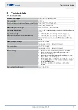
Страница 7: ...Technical clarification with TROX required for some sizes Closed damper leakage EN 1751 Class 2 Nominal size B H 840 x 480 Class 3 Casing leakage EN 1751 Class B Nominal size B H 840 x 480 Class C EC...

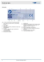
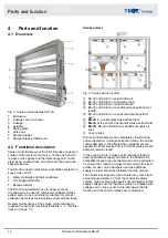
Страница 8: ...the CE marking was affixed 7 Year of manufacture 8 Manufacturer s address 9 Notified body 10 Regulated characteristics the fire resistance class depends on the application and may vary 5 1 Installati...

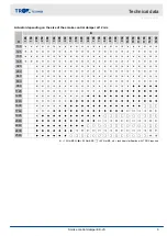
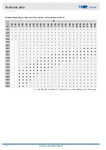
Страница 9: ...0 400 450 520 550 600 680 700 750 840 850 900 950 1000 1050 1100 1150 1200 1250 100 125 150 165 320 480 640 800 960 1120 1280 1440 1600 1760 1920 2080 2240 2400 2560 15 Nm BEN 25 Nm BEE 40 Nm BE techn...

Страница 10: ...0 400 450 520 550 600 680 700 750 840 850 900 950 1000 1050 1100 1150 1200 1250 100 125 150 165 320 480 640 800 960 1120 1280 1440 1600 1760 1920 2080 2240 2400 2560 15 Nm BEN 25 Nm BEE 40 Nm BE techn...

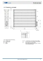
Страница 11: ...ide B Width H Height B x H nominal size area exposed to the airflow Keep area free for accessibility of the actuator Fixing option for control module Fixing with self tapping screws 4 2 x 9 5 mm to be...

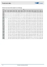
Страница 12: ...28 29 30 31 32 33 34 35 35 36 37 960 20 21 22 23 24 25 26 27 28 29 30 31 32 33 34 35 36 37 38 39 40 42 1120 22 23 24 25 27 28 29 30 31 32 33 34 36 37 38 39 40 42 43 44 45 46 1280 24 25 27 28 29 30 32...

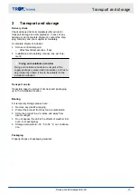
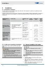
Страница 13: ...of the supply package unless stated otherwise but has to be provided by others it has to be suitable for the installation situation Transport on site If possible take the product in its transport pac...

Страница 14: ...K JZ or EK2 EU on solid shaft wall EK JZ or EK2 EU on a vertical smoke extract duct shaft EK JZ or EK2 EU on a horizontal smoke extract duct EK JS in a horizontal smoke extract duct EK JS at the end o...

Страница 15: ...entilation can be enabled in combined systems with smoke control dampers Depending on the system layout the damper blade can be fully opened fully closed or in the intermediate position Depending on w...

Страница 16: ...d i o S 28 in a vertical duct E600 120 hod i o S 30 at the end of a vertical duct 32 Vertical solid smoke extract ducts Operating temperature up to 600 C on a vertical duct E600 120 ved i o S 34 LE As...

Страница 17: ...zontal or lying down The position of the actuator is not critical but it must remain accessible for maintenance 5 3 1 High temperature sealing tape High temperature sealing tape is used to seal betwee...

Страница 18: ...ing tempera tures Hexagon bolts M8 with 2 washers and nuts to be provided by others Duct clips or self tapping screws 5 5 x 22 mm to be provided by others HT sealing tape accessories or to be provided...

Страница 19: ...ape to the flange of the smoke control damper for sealing 3 Manufacture suspension for smoke control damper 5 6 Suspending the smoke control damper on page 36 4 Screw smoke control damper to the sheet...

Страница 20: ...Hexagon bolts M8 with 2 washers and nuts to be provided by others Duct clips or self tapping screws 5 5 x 22 mm to be provided by others HT sealing tape accessories or to be provided by others Duct cl...

Страница 21: ...ape to the flange of the smoke control damper for sealing 3 Manufacture suspension for smoke control damper 5 6 Suspending the smoke control damper on page 36 4 Screw smoke control damper to the sheet...

Страница 22: ...tures Hexagon bolts M8 with 2 washers and nuts to be provided by others Duct clips or self tapping screws 5 5 x 22 mm to be provided by others HT sealing tape accessories or to be provided by others D...

Страница 23: ...o the flange of the smoke control damper for sealing 3 Manufacture suspension for smoke control damper 5 6 Suspending the smoke control damper on page 36 4 Screw smoke control damper to the sheet stee...

Страница 24: ...Hexagon bolts M8 with 2 washers and nuts to be provided by others Duct clips or self tapping screws 5 5 x 22 mm to be provided by others HT sealing tape accessories or to be provided by others Duct cl...

Страница 25: ...ape to the flange of the smoke control damper for sealing 3 Manufacture suspension for smoke control damper 5 6 Suspending the smoke control damper on page 36 4 Screw smoke control damper to the sheet...

Страница 26: ...or self tapping screws 5 5 x 22 mm to be provided by others HT sealing tape accessories or to be provided by others Suspension bracket fixed with 2 self tapping screws 5 6 Suspending the smoke contro...

Страница 27: ...tions 2 Apply HT sealing tape to the flange of the smoke control damper for sealing 3 Manufacture suspension for smoke control damper 5 6 Suspending the smoke control damper on page 36 4 Screw smoke c...

Страница 28: ...Hexagon bolts M8 with 2 washers and nuts to be provided by others Duct clips or self tapping screws 5 5 x 22 mm to be provided by others HT sealing tape accessories or to be provided by others Duct cl...

Страница 29: ...tape to the flange of the smoke control damper for sealing 3 Manufacture suspension for smoke control damper 5 6 Suspending the smoke control damper on page 36 4 Screw smoke control damper to the shee...

Страница 30: ...ts to be provided by others Duct clips or self tapping screws 5 5 x 22 mm to be provided by others HT sealing tape accessories or to be provided by others Suspension bracket fixed with 2 self tapping...

Страница 31: ...ctions 2 Apply HT sealing tape to the flange of the smoke control damper for sealing 3 Manufacture suspension for smoke control damper 5 6 Suspending the smoke control damper on page 36 4 Screw smoke...

Страница 32: ...others Duct clips or self tapping screws 5 5 x 22 mm to be provided by others HT sealing tape accessories or to be provided by others Suspension bracket fixed with 2 self tapping screws 5 6 Suspendin...

Страница 33: ...to the flange of the smoke control damper for sealing 3 Manufacture suspension for smoke control damper 5 6 Suspending the smoke control damper on page 36 4 Screw smoke control damper to the sheet ste...

Страница 34: ...thers Flange to be provided by others 54 HT sealing tape to be provided by others Self tapping screws 4 2 x 16 mm to be provided by others Wallplug with fire safety engineering certification and threa...

Страница 35: ...e flange to be provided by others to the EK JS with self tapping screws 3 For sealing stick the HT sealing tape onto the flange 4 Drill the holes on the shaft wall according to the hole pattern on the...

Страница 36: ...ion Use only fire rated steel anchors with suitability certifi cate Instead of anchors you can use threaded rods and secure them using nuts and washers 5 6 3 Suspended installation Fig 16 EK JS suspen...

Страница 37: ...mper is not affected connection according to assembly and operating manual of the smoke control damper The sizing of the smoke extract duct used remains the responsibility of the system installer and...

Страница 38: ...The flexible connectors should meet the specifications for the sheet steel smoke extract duct Be sure to follow the manufacturer s instructions 6 2 Cover grilles Fig 20 EK JS with a cover grille EK JS...

Страница 39: ...lication it must be ensured that the con tacts of the auxiliary switches can no longer be used in the milliampere range once they have been wired up to a relatively high current A combination of mains...

Страница 40: ...W 12 W Power consumption when idle 0 1 W 0 5 W Power consumption rating 6 VA 5 VA 18 VA 8 2 A Imax 5 ms 8 2 A Imax 5 ms Torque 15 Nm 25 Nm 40 Nm Run time 30 s 90 60 s 90 60 s 90 Limit switch Type of...

Страница 41: ...when idle 0 4 W 0 5 W Power consumption rating 7 VA 6 VA 15 VA 4 A Imax 5 ms 7 9 A Imax 5 ms Torque 15 Nm 25 Nm 40 Nm Run time 30 s 90 60 s 90 60 s 90 Limit switch Type of contact 2 changeover contact...

Страница 42: ...on observe the following instructions Chapter 7 2 Wiring and connection to the central BMS on page 39 Technical data of continuously controlled actuators Order code detail B24 SR Actuator BEN24 SR TR...

Страница 43: ...dividually or as part of an overall system and according to the control matrix set up for the event of a fire In this case the control system of the mechan ical smoke extract system or pressurisation...

Страница 44: ...Technical data for the control module Order code detail B24A B24AM B24AS Control module AS EM EK AS EM M AS EM SIL2 Supply voltage 26 5 31 6 V DC Current consumption 450 mA 450 mA 400 mA from AS i Max...

Страница 45: ...ical data for the control module Order code detail B24BKNE Control module BKNE230 24 Nominal voltage AC 230 V 50 60 Hz Functional range AC 198 264 V Rating 19 VA including actuator Power consumption 1...

Страница 46: ...factory wired Technical data of the actuator 7 3 2 B230 on page 41 Chapter 7 3 1 B24 on page 40 Connection data Order code detail B24C Control module BC24 G2 Supply voltage Provided by the SLC con tro...

Страница 47: ...module BRM 10 F ST BRM 10 F Electrical data Supply voltage 18 32 V DC typically 24 V Current consumption 5 mA typically 26 mA max for 100 ms when relays close Protection level IP 20 EN 60529 IEC prote...

Страница 48: ...conductors Solid core 0 2 1 5 mm Multi strand without ferrule 0 2 1 5 mm Multi strand insulated ferrule 0 25 0 75 mm Multi strand non insulated ferrule 0 25 1 5 mm Ambient conditions Ambient temperat...

Страница 49: ...oes not impair the function of the damper The damper blades seals adapt themselves to the seal and can compensate for the smallest devia tions Important Install the smoke control damper without tor si...

Страница 50: ...mpers are installed country specific regulations may apply Maintenance The smoke control damper and the actuator are mainte nance free with regard to wear but smoke control dampers must still be inclu...

Страница 51: ...r for damage Smoke control damper damper blades and seal have to be intact Repair or replace the smoke control damper Specialist personnel Functional test of the smoke control damper 8 2 Functional te...

Страница 52: ...h off the power supply before working on any electrical equipment 1 Disconnect the wiring 2 Remove the smoke extract ducts 3 Remove the smoke control damper Disposal ENVIRONMENT Risk of harm to the en...

Страница 53: ...Decommissioning removal and disposal Smoke control damper EK JS 53...

Страница 54: ...11 Flange dimensional drawing Flange dimensional drawing Smoke control damper EK JS 54...

Страница 55: ...de Pba Spacing of the outer holes on width side Nba Pitch of the outer holes on width side K Sum of the distances of the outer holes on height side Pha Spacing of the outer holes on height side Nha Pi...

Страница 56: ...ion in a horizontal smoke extract duct 18 20 22 24 32 in a vertical smoke extract duct 30 on a vertical smoke extract duct 28 on a vertical solid smoke extract duct 34 on solid shaft walls 34 Installa...

Страница 57: ...Smoke control damper EK JS 57...

Страница 58: ...Smoke control damper EK JS 58...

Страница 59: ...Smoke control damper EK JS 59...

Страница 60: ...Valid from 01 2022 TROX GmbH Heinrich Trox Platz 47504 Neukirchen Vluyn Ger many Germany Phone 49 0 2845 2020 49 0 2845 202 265 E mail trox trox de http www troxtechnik com...

Отзывы: