7.4.1 TROXNETCOM B24A, B24AM, B24AS
A controller (master) communicates with the control modules (slaves, up to 31 per master)
Free bus topology of the two-wire cable for data and energy
Simple and intelligent wiring system
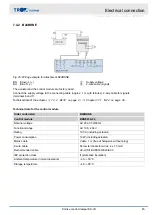
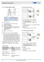
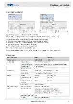
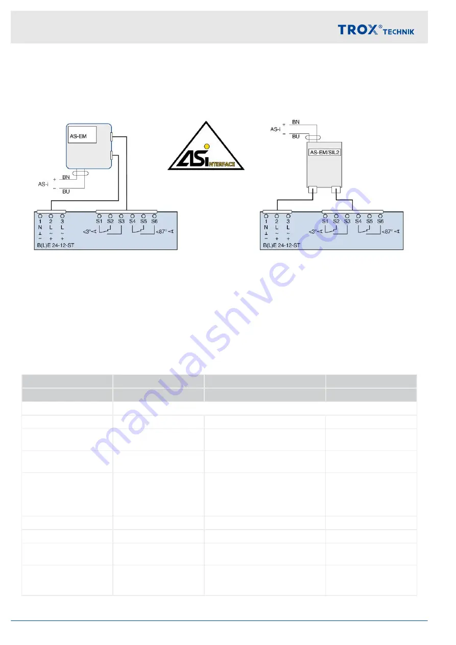
Fig. 24: Wiring example for attachments B24A and B24AS
BN Brown (+)
BU Blue (–)
The actuator and the AS-i control module are factory wired.
An AS-i bus (+/–) is used for both voltage supply and signals.
The connecting cables of the AS-EM/SIL module are fitted with wire end ferrules.
Technical data of the actuator,
Chapter 7.3.1 ‘B24 ’ on page 40
.
Technical data for the control module
Order code detail
B24A
B24AM
B24AS
Control module
AS-EM/EK
AS-EM/M
AS-EM/SIL2
Supply voltage
26.5 – 31.6 V DC
Current consumption
450 mA
450 mA
< 400 mA from AS-i
Max. current load per
output
400 mA
400 mA
340 mA
Max. current load per
module
400 mA
400 mA
340 mA
Interfaces
4 inputs/3 outputs
4 inputs/3 outputs
2 outputs with transistor
(typically 24 V DC from
AS-i, voltage range 18 –
30 V)
Operating temperature
-5 to 75 °C
-5 to 75 °C
-20 to 70 °C
Storage temperature
-5 to 75 °C
-5 to 75 °C
-20 to 75 °C
Protection level, IEC pro-
tection class
IP 42
IP 42
IP 54
AS-i profile
S7.A.E
S7.A.E
S-7.B.E (Safety at Work)
and S7.A.E (motor
module)
Electrical connection
Actuator with control module > TROXNETCOM B24A, B24AM, B24AS
Smoke control damper EK-JS
44
Содержание EK-JS
Страница 53: ...Decommissioning removal and disposal Smoke control damper EK JS 53...
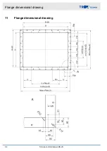
Страница 54: ...11 Flange dimensional drawing Flange dimensional drawing Smoke control damper EK JS 54...
Страница 57: ...Smoke control damper EK JS 57...
Страница 58: ...Smoke control damper EK JS 58...
Страница 59: ...Smoke control damper EK JS 59...

