


12
EN
digital true RMS multimeter BE52
Continuity test
Warning of electrical voltage
Before carrying out resistance, continuity or diode
measurements, switch off the current of the electric
circuit and discharge all capacitors.
1. Set the rotary switch to the
Ω/
/CAP
(20) position,
then use the MODE button (15) to select the continuity test
( indication).
2. Insert the plug of the red measuring tip into the
V/Ω
measuring socket (5) and the plug of the black
measuring tip into the
COM
measuring socket (6).
3. Connect the measuring lines to the circuit to be tested.
ð
When the circuit is closed and the resistance is smaller
than 50 Ω, an acoustic signal is emitted.
ð
When the circuit is open,
OL
is displayed.
Diode testing
Warning of electrical voltage
Before carrying out resistance, continuity or diode
measurements, switch off the current of the electric
circuit and discharge all capacitors.
1. Set the rotary switch to the
Ω/
/CAP
(20) position,
then use the MODE button (15) to select the diode test
(
and V indication).
2. Insert the plug of the red measuring tip into the
V/Ω
measuring socket (5) and the plug of the black
measuring tip into the
COM
measuring socket (6).
3. Connect the measuring tips to the diode. If the
OL
indication (exceedance of the measuring range) is
displayed, swap the measuring tip connections at the
diode.
ð
The following indications may typically be displayed:
- 0.400 to 0.700 V: Diode ok
- indications near 0 V: Circuit short-circuited
- OL: open circuit (in both polarities)
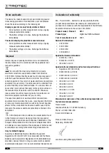
Example:
Measuring capacitance
Before carrying out capacitance measurements, observe the
following:
•
Discharge each capacitor before carrying out a
measurement! Residual voltage in the capacitor can lead
to a destroyed measuring device!
•
Never connect the measuring inputs to a voltage source.
This will destroy the measurement device.
•
For reasons of safety, measure whether there is a residual
charge in the capacitor (using the VDC range) before you
perform a capacitance measurement.
1. Set the rotary switch to the
Ω/
/CAP
position (20),
then use the
MODE
button (15) to select the capacitance
measurement (
nF
indication).
2. Insert the plug of the red measuring tip into the
V/Ω
measuring socket (5) and the plug of the black
measuring tip into the
COM
measuring socket (6).
3. Connect the capacitor to be tested to the measuring tips.
Electrolytic capacitors must be connected with correct
polarity (red to plus, black to minus).
Since the charging processes within the capacitor require
a certain amount of time, the indication will be delayed by
up to 3 minutes. This delay is systemic, not a malfunction.
Wait until the displayed value has stabilized before reading
the measured value.
ð
The measured value will be indicated on the display.
Note:
In case of a defective capacitor zero will be displayed.
Bear in mind that electrolytic capacitors can come with a
substantial scattering within their tolerance range.
Residual voltages in the capacitor or damaged insulating layers/
dielectrics can lead to significantly falsified results.
Measuring frequency/duty cycle
1. Set the rotary switch to the
Hz%
position (18), then use the
MODE
button (15) to select the desired measurement
mode (for frequency:).
Hz
indication, for duty cycle:
% indication
).
2. Insert the plug of the red measuring tip into the
V/Ω
measuring socket (5) and the plug of the black
measuring tip into the
COM
measuring socket (6).
3. Connect the measuring tips to the measuring object.
ð
Depending on the selection with the
MODE
button (15),
the frequency or the duty cycle is shown.


