background image

44          TX6356-UM-EN-01

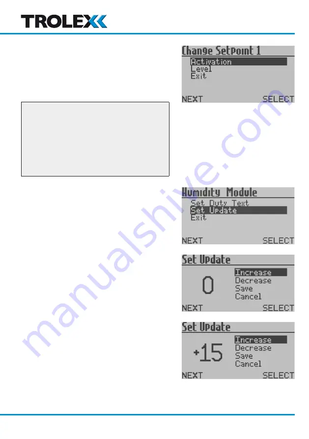
Set Update

The value of the analogue input signal is 

averaged and up-dated at periodic intervals. 

You can configure the up-date period in the 

Set Update Menu

.

Checkpoint

A low 

Set Update

 setting will give rapid 

reaction to the input signal and a higher 

setting may be entered where damping of 

a fluctuating input is necessary, or simply 

as a means of applying a delay to the input. 

This is particularly useful in electrically 

noisy environments.

From the 

Configuration Setup Menu

 press 

L

, navigate to 

Set Update

 and press 

R

 to 

enter the 

Set Update Menu

.

Press 

L

 to navigate to 

Increase

 or 

Decrease


as required. The field is configurable between 

0 and 99 seconds.

Press 

R

 to 

Increase

 or 

Decrease 

as required. 

Press 

L

 and select 

Save

 or 

Cancel

 as 

required. Press 

R

 to confirm the selection 

and return to the 

Configuration Setup 

Menu

.

www.trolex.com

Содержание TX6356

Страница 1: ......

Страница 2: ......

Страница 3: ...485 Data Output Signal 14 4 Setup and Calibration 16 4 1 Controls and Indicators 16 4 2 Software Menus 18 4 3 Navigation 19 4 4 Power up 20 4 5 Main Menu 21 4 5 1 Sentro Setup 22 4 5 2 Output Setup 27 4 5 3 Module Setup 38 4 5 4 Exit 45 4 6 Support 45 5 Operation 46 5 1 Dual Relay Contact Output Signal 46 5 1 1 To Reset a Latched Relay 46 6 Diagnostics and Maintenance 48 6 1 Diagnostic Messages 48...

Страница 4: ...ng sensor head For safety monitoring of humidity in heavy duty applications 12 V dc intrinsically safe Group 1 Underground Mining TX6356 00 01 04 05 06 Sentro Humidity Sensor with bottom projecting sensor head For safety monitoring of humidity in heavy duty applications 24 V dc General Purpose www trolex com ...

Страница 5: ...necting heavy plant cables Sensing range 10 to 90 RH non condensing Sensing accuracy 5 1 2 Application Fixed point humidity sensor for safety monitoring of humidity in heavy duty applications Suitable for use in mining storage areas process plants utilities and oil gas 1 3 Product Options Bottom Projecting Sensor Output Order Reference Group 1 Underground Mining Ex ia General Purpose 4 to 20 mA ou...

Страница 6: ...6 TX6356 UM EN 01 1 4 Dimensions www trolex com ...

Страница 7: ...D screen Mounting Two 6 5 mm diameter fixing holes with Unistrut 6946 indents Cable entries 1 x M20 Electrical connections 4 mm barrier clamp terminals with circuit segregation barriers Conductors A maximum of two per terminal Conductor size A maximum of 2 x 2 5 mm Terminal torque 2 4 Nm maximum Vibration limits Vibration limits EN 60079 29 1 10 to 30 Hz 1 00 mm total excursion 31 to 150 Hz 19 6 m...

Страница 8: ...up 1 10 to 14 V dc Minimum line load Group 1 10 K ohms Supply current Group 1 20 mA 12 V dc 4 to 20 mA Output Signal 3 4 wire remote powered Supply voltage Group 1 10 to 14 V dc General Purpose 18 to 28 V dc Maximum line load Group 1 220 ohm at 12 V dc General Purpose 500 ohm at 24 V dc Supply current Group 1 48 mA 12 V dc General Purpose 40 mA 24 V dc 5 to 15 Hz Output Signal 3 4 wire remote powe...

Страница 9: ...dentification sensing range and specific calibration This data is automatically recognised by the Sentro when the sensing module is loaded into the module bay The sensing modules are pre calibrated so they can be replaced at any time by a replacement sensing module The sensing module will identify itself when plugged into the sensor housing and auto configuration will take place All Sentro sensing...

Страница 10: ...Model Field Screw Terminals Ui li Ci Li Pi TX6356 06 01 4 to 20 mA 5 WRT 6 14 4 V 1 0 0 1 WRT 2 or 3 TX6356 06 02 0 4 to 2 V 5 WRT 6 14 4 V 1 0 0 1 WRT 2 or 3 TX6356 06 03 5 to 15 Hz 5 WRT 6 14 4 V 1 0 0 1 WRT 2 16 5 V 0 0 2 5 W TX6356 06 04 RS485 5 WRT 6 14 4 V 1 0 0 1 WRT 2 2 WRT 3 6 88 V 1 0 0 TX6356 06 05 dual relay normally closed 5 WRT 6 14 4 V 1 0 0 1 WRT 2 30 V 1 0 0 3 WRT 4 30 V 1 0 0 TX6...

Страница 11: ...Hz 5 WRT 6 1 WRT 2 0 0 0 0 0 TX6356 06 04 RS485 5 WRT 6 1 WRT 2 2 WRT 3 5 88 V 66 mA 97 mW 3 26 mH TX6356 06 05 dual relay normally closed 5 WRT 6 1 WRT 2 0 0 0 0 0 3 WRT 4 0 0 0 0 0 TX6356 06 06 dual relay normally open 5 WRT 6 1 WRT 2 0 0 0 0 0 3 WRT 4 0 0 0 0 0 1 Ii Not critical 2 Lo Is calculated using the formula Lo Io 1 5 2 525 uJ 3 Co Co 1 uF unless the conditions stated in 60079 11 2011 Cl...

Страница 12: ...ld also be made to those responsible for the engineering layout and topology of the plant as they will be most familiar with the nature of the potential dangers and the most likely sources of high humidity Sensor coverage cannot be simply expressed in terms of number per unit area Sensors need to be sited where they are capable of monitoring those parts of a plant where humidity may accumulate or ...

Страница 13: ...t signal from terminals 1 and 2 is a low impedance two wire voltage output Can be configured as 3 or 4 wire 3 4 2 4 to 20 mA Analogue Output Signal The output signal from terminals 1 and 2 is a conventional 4 to 20 mA two wire current regulated signal loop Can be configured as 3 or 4 wire www trolex com ...

Страница 14: ... at the monitoring device 3 4 4 Dual Relay Contact Dual independent relay contacts for remote signalling and control Setpoint values for General and High alarms may be adjusted to preference 3 4 5 RS485 Data Output Signal RS485 serial data output with analogue signal intelligence Use in conjunction with a PC for data display and setpoint alarm warnings www trolex com ...

Страница 15: ...ty label of the sensor Physical layer RS485 Protocol Trolex proprietary Connection mode Modbus Number of points 32 Maximum distance 1 000 m Recommended cable specified in BS5308 Part 1 for locally powered sensors 1 twisted pair 0 5 mm2 Overall screen Recommended cable for sensors that are powered through the data cable 2 twisted pair 0 5 mm2 Individual overall screen www trolex com ...

Страница 16: ...16 TX6356 UM EN 01 4 Setup and Calibration 4 1 Controls and Indicators www trolex com ...

Страница 17: ...TX6356 User Manual TX6356 UM EN 01 17 www trolex com ...

Страница 18: ...18 TX6356 UM EN 01 4 2 Software Menus www trolex com ...

Страница 19: ...ons is abbreviated to L and R throughout this User Manual To access the L Next and R Select Change buttons you need to remove the front cover Use a cross head screwdriver to remove the four screws securing the front cover and move it out of the way Checkpoint The Sentro Humidity Sensor is factory configured with the Security Code unset If a Security Code has been subsequently set it will need to b...

Страница 20: ...he Start up Screen will appear The Start up Screen displays basic information about the system including the software version driver version and output type Power On After five seconds the Main Display will appear The Main Display displays the current humidity level www trolex com ...

Страница 21: ...or may be set up according to preference The available menus are as follows Sentro Setup Output Setup Module Setup Exit Checkpoint You can safely remove the front cover of the Sentro Humidity Sensor for setup in a hazardous area even with the power applied Checkpoint The Sentro Humidity Sensor will automatically return to the Main Display if no keys are pressed within 30 seconds www trolex com ...

Страница 22: ...Setup Menu The available menus are as follows System Information Display Setup Alert Setup Set Security Code Exit 4 5 1 1 System Information This displays basic information about the system including the main software version system date system time driver versions and output formats From the Sentro Setup Menu press L navigate to the System Information and press R to display the System Information...

Страница 23: ...Set Backlight Adjust Contrast Exit Set Backlight The screen backlight illumination may be set to On or Off to reduce power consumption From the Display Setup Menu press L navigate to Set Backlight and press R to enter the Set Backlight Menu From the Set Backlight Menu press R to set the Backlight Illumination to On or Off as required Press L to move to Save or Cancel as required Press R to confirm...

Страница 24: ...required Press L and select Save or Cancel as required Press R to confirm the selection and return to the Display Setup Menu Exit From the Display Setup Menu press L navigate to Exit press R to confirm the selection and return to the Sentro Setup Menu 4 5 1 3 Alert Setup Menu This enables you to carry out the setup of the Alerts From the Sentro Setup Menu press L navigate to Alert Setup and press ...

Страница 25: ...ancel as required Press R to confirm the selection and return to the Alert Setup Menu Confidence Alarm The Confidence Alarm flash can be set to On or Off For details of the Confidence Alert refer to Section 5 From the Alert Setup Menu press L navigate to Confidence Alarm and press R to enter the Confidence Alarm Menu From the Confidence Alarm Menu press R to set the Confidence Alert to On or Off a...

Страница 26: ...ntro Setup Menu press L navigate to Set Security Code and press R to enter the Set Security Code menu From Set Security Code press R to increment the first digit Press L to confirm the selection and move to the next digit Repeat for all four digits Press L and navigate to Save or Cancel as required and Press R to confirm the selection 4 5 1 5 Exit From the Sentro Setup Menu press L navigate to Exi...

Страница 27: ... 20 mA analogue output signal 5 to 15 Hz output Dual relay contacts RS485 digital output signal Each of the five signal types has a unique set of menus that enable you to view and configure characteristics of the output signal All five sets of menus are described in the following sections From the Main Menu press L navigate to Output Setup and press R to enter the Output Setup Menu 4 5 2 1 0 4 to ...

Страница 28: ...transmitted output signal when the Sentro Humidity Sensor is measuring zero humidity can be trimmed or offset From the Output Setup Menu press L navigate to Trim Output Zero and press R to enter the Trim Output Zero Menu Press L to navigate to Increase or Decrease as required Press R to Increase or Decrease the Output Zero as required Press L and select Save or Cancel as required Press R to confir...

Страница 29: ...e to Increase or Decrease as required Press R to Increase or Decrease the Output Span as required Press L and select Save or Cancel as required Press R to confirm the selection and return to the Output Setup Menu Reset Output This enables you to reset the Zero and Span output signal levels back to the default factory settings From the Output Setup Menu press L navigate to Reset Output and press R ...

Страница 30: ...mation Trim Output Zero Trim Output Span Reset Output Exit Output Information This displays the factory set output signal type for the Sentro Humidity Sensor From the Output Setup Menu press L navigate to Output Information and press R to display the Output Information Trim Output Zero The level of the transmitted output signal when the Sentro Humidity Sensor is measuring zero humidity can be trim...

Страница 31: ...and return to the Output Setup Menu Trim Output Span The level of the transmitted output signal when the Sentro Humidity Sensor is measuring a given humidity level can be trimmed or offset From the Output Setup Menu press L navigate to Trim Output Span and press R to enter the Trim Output Span Menu Press L to navigate to Increase or Decrease as required Press R to Increase or Decrease the Output S...

Страница 32: ... Output and press R to enter the Reset Output menu Press L to navigate to Restore Defaults and press R to confirm the selection Exit From the Output Setup Menu press L navigate to Exit press R to confirm the selection and return to the Main Menu 4 5 2 3 5 to 15 Hz Output Signal The available menus are Output Information Trim Output Zero Trim Output Span Reset Output Exit www trolex com ...

Страница 33: ...of the transmitted output signal when the Sentro Humidity Sensor is measuring zero humidity can be trimmed or offset From the Output Setup Menu press L to navigate to Trim Output Zero Press R to enter the Trim Output Zero Menu Press L to navigate to Increase or Decrease as required Press R to Increase or Decrease the Output Zero as required Press L to navigate to Save or Cancel as required Press R...

Страница 34: ...ase or Decrease as required Press R to Increase or Decrease the Output Span as required Press L and select Save or Cancel as required Press R to confirm the selection and return to the Output Setup Menu Reset Output This enables you to reset the Zero and Span output signal levels back to the default factory settings From the Output Setup Menu press L navigate to Reset Output and press R to enter t...

Страница 35: ... and Set Relay 2 Mode This enables you to setup the operating function of each relay Each Relay can be independently setup Checkpoint Set Relay 1 Mode and Set Relay 2 Mode are configured in exactly the same way as each other Checkpoint A relay can be configured to Latch or Automatically Reset according to preference From the Output Setup Menu press L navigate to Set Relay 1 Mode or Set Relay 2 Mod...

Страница 36: ...ed Exit From Set Relay 1 Mode or Set Relay 2 Mode press L navigate to Exit and press R to confirm the selection and return to the Output Setup Menu 4 5 2 5 RS485 Data Output Signal The available menus are as follows Modbus Address Baud Rate TxOn Delay TxOff Delay Exit Modbus Address The Modbus Address can be set between 1 and 255 as required From the Output Setup Menu press L navigate to Modbus Ad...

Страница 37: ...e Baud Rate can be set to 300 600 1200 2 400 4800 9600 14400 19200 28800 38400 57600 115200 as required From the Output Setup Menu press L navigate to Baud Rate and press R to enter the Set Baud Rate Menu Press R to navigate to the required Baud Rate press L and select Save or Cancel as required Press R to confirm the selection and return to the Output Setup Menu TxOn Delay andTxOff Delay Checkpoi...

Страница 38: ...to Increase or Decrease as required Press L and select Save or Cancel as required Press R to confirm the selection and return to the Output Setup Menu Exit From the Output Setup Menu press L navigate to Exit press R to confirm the selection and return to the Main Menu 4 5 3 Module Setup This enables you to setup the functional values of the Sentro Module fitted to Sentro Humidity Sensor From the M...

Страница 39: ...ing Setup Menu The available menus are as follows Lower Range Upper Range Exit Lower Range and Upper Range Set the desired Lower Range and Upper Range of the displayed reading for a given magnitude of input signal This can be any numeric value and the polarity can be any negative value through to any positive value From the Scaling Setup Menu press L navigate to Lower Range or Upper Range as requi...

Страница 40: ...g Setup Menu press L navigate to Exit and press R to Exit the Scaling Setup Menu and return to the Module Setup Menu 4 5 3 2 Setpoint 1 and Setpoint 2 This enables you to carry out a setup of Setpoint 1 and Setpoint 2 Checkpoint Setpoint 1 and Setpoint 2 are configured in exactly the same way From the Module Setup Menu press L navigate to Setpoint 1 or Setpoint 2 and press R to enter the Setpoint ...

Страница 41: ...Menu press R to set Activation to Over or Under as required Press L and navigate to Save or Cancel as required Press R to confirm the selection and return to the Setpoint 1 or Setpoint 2 Setup Menu Level The Level at which Setpoint 1 and Setpoint 2 are activated can be configured Checkpoint The default setting for Setpoint 1 is 40 and for Setpoint 2 is 65 From the Setpoint 1 or Setpoint 2 Setup Me...

Страница 42: ...Setpoint 2 Setup Menu Exit From the Setpoint 1 or Setpoint 2 Setup Menu press L navigate to Exit press R to confirm the selection and return to the Module Setup Menu 4 5 3 3 Configuration This enables you to setup the Configuration of the sensing module From the Module Setup Menu press L navigate to Configuration and press R to enter the Configuration Setup Menu The available menus are as follows ...

Страница 43: ... character as required and press L to move to the next character Checkpoint The characters are in the sequence A to Z 0 to 9 and a Blank Space Checkpoint If you wish to clear all text press L navigate to ClearText and press R to clear all DutyText as required Checkpoint The maximum number of characters that can be entered in the DutyText field is 16 Press L and select Save or Cancel as required Pr...

Страница 44: ...put is necessary or simply as a means of applying a delay to the input This is particularly useful in electrically noisy environments From the Configuration Setup Menu press L navigate to Set Update and press R to enter the Set Update Menu Press L to navigate to Increase or Decrease as required The field is configurable between 0 and 99 seconds Press R to Increase or Decrease as required Press L a...

Страница 45: ... navigate to Exit and press R to confirm the selection and return to the Main Menu 4 5 4 Exit From the Main Menu press L navigate to Exit and press R to confirm the selection and return to the Main Display 4 6 Support If you need technical support to operate this product or would like details of our after sales technical support packages please contact your local Trolex service agent or service tr...

Страница 46: ... Humidity Sensor the functional mode and status of the relays can be displayed at any time Press L and the relay state will be displayed 5 1 1 To Reset a Latched Relay If a relay is latched during operation reset it as follows From the Main Display press R to open the Unlatch Relays menu The available menus are as follows Unlatch Relay 1 Unlatch Relay 2 Go to Main Menu Exit 5 1 1 1 Unlatch Relay 1...

Страница 47: ...ess L to navigate to Unlatch Relay 1 or Unlatch Relay 2 and press R to confirm the selection 5 1 1 2 Go to Main Menu From the Unlatch Relays Menu press L navigate to Go to Main Menu press R and return to the Main Menu 5 1 1 3 Exit From the Unlatch Relays Menu press L navigate to Exit press R and return to the Main Display Checkpoint A relay configured to Latch cannot be reset until the initiating ...

Страница 48: ... Fitted If the sensing module has been removed from the Sentro Humidity Sensor and is out for more than 10 seconds an error message will be shown 6 2 Maintenance 6 2 1 Introduction To keep your Sentro Humidity Sensor in the best possible condition and minimise downtime Trolex strongly recommends that you carry out regular planned preventative maintenance and keep records of the maintenance carried...

Страница 49: ... and is securely fitted 3 Check the LCD screen is clear and free from damage 4 If any part of the Sentro Humidity Sensor shows any signs of damage deformation or missing parts contact your local Trolex service agent or service trolex com for advice on repair or replacement 5 After the completion of all maintenance update the maintenance records Equipment Name TaskType Task Number Interval Sentro H...

Страница 50: ... not use sharp tools as this may cause damage to the humidity sensor 3 After the completion of all maintenance update the maintenance records 6 2 4 Sentro Humidity Sensor Output Signal Check 1 Using a test meter check that the value of the output signal agrees with the value of the display reading 2 After the completion of all maintenance update the maintenance records www trolex com ...

Страница 51: ...ion of all maintenance update the maintenance records 6 3 Disposal Part of the ethos of Trolex is sustainable design The Sentro Humidity Sensor contains materials that can be recovered recycled and reused At the end of its useful life ensure that the Sentro Humidity Sensor is recycled in accordance with local laws and bylaws for the geographic area where it is located The end of its useful life is...

Страница 52: ...ss and keep good maintenance records Consult your local Trolex service agent or the Trolex Product Support Department service trolex com for help in implementing a planned preventative maintenance process The Maintenance Log gives an example of a typical maintenance record system www trolex com ...

Страница 53: ... Manual TX6356 UM EN 01 53 6 5 Maintenance and Calibration Log Order Reference TX6356 Serial Number Date Purchased Location Flow Rate Date Scheduled Check Fault Recalibrate Return to Trolex Comments www trolex com ...

Страница 54: ... please notify us at marketing trolex com No part of this document may be reproduced in any form or by any means electronic or mechanical including photocopying without express written permission of Trolex All pertinent state regional and local safety regulations must be observed when installing and using this product For reasons of safety and to help ensure compliance with documented system data ...

Страница 55: ......

Страница 56: ......

Отзывы: