background image

Bar Mixer Shower

13

IMPORTANT:

 These bar mixer brackets 

are designed to be mounted onto a solid 
structure. If installing to a stud partition wall, 
dry lined wall or similar, it is recommended 
that the brackets are secured to the studs 
or noggins. In this case, the pipework to the 
brackets should pass through the support 
studs or noggins via a suitably sized hole 

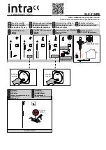
(fig.11)

.

Decide upon the mounting position of the 
brackets on the wall and mark the centres.
Check the mounting marks are level and that the 
distance between them is equal to the distance 
between the bar mixer inlet centres 

(fig.12)

.

Mark the route of the pipework to the brackets. 
Remove the plaster and brickwork (or 
plasterboard) to the depth required and chase 
out additional areas of the wall to allow for the 
incoming pipework. Make sure that enough solid 
structure of wall remains around the chasing to 
accommodate the mounting plate wall plugs 
and screws 

(fig.13)

.

Complete the pipework to the bracket mounting 
points. Leave an excess of pipe protruding out 
of the wall of approximately 60mm as measured 
from the face of the finished wall or tiles 

(fig.14)

.

Flush the pipework through to remove 
any debris. Check for leaks and remedy as 
necessary.

Make good the wall and tiles. Make sure that the 
pipes exiting the wall are free and can move in 
and out of the wall by a minimum distance of 
4mm


(fig.10)

.

Level

Bracket mounting position

150 mm

Equal to the distance between

the bar mixer inlet centres

 T00345

 T00357

Approximately

60 mm

Finished

wall

 T00365

 T00356

54 mm

Mounting

plate

Mounting

holes

Pipework

Chased out

area

Fig.11

Fig.12

Fig.13

Fig.14

Содержание DENE HI-FLO

Страница 1: ...ER BY TEL 024 7637 8321 INSTALLATION AND OPERATING INSTRUCTIONS Please read this book thoroughly and familiarise yourself with all instructions before commencing installation and keep it for future re...

Страница 2: ...OUTLET TEMPERATURES 17 OPERATING THE SHOWER 18 SPARE PARTS 19 TMV2 REQUIREMENTS 12 MONTHLY VERIFICATION 20 APPROVALS 20 FLOW RATES 20 MAINTENANCE 21 FAULT FINDING 22 23 GUARANTEE SERVICE POLICY ETC r...

Страница 3: ...Mixer Shower 3 All dimensions listed in this fitting book regarding the product and installation are approximate MAIN COMPONENTS Fig 1 A Thermostatic bar mixer valve B Push fit connector x2 with trims...

Страница 4: ...Bar Mixer Shower 4 All dimensions listed in this fitting book regarding the product and installation are approximate 290mm 55mm DIMENSIONS...

Страница 5: ...ixer shower Water Minimum Flow Rate For best performance within the specified running pressure range a minimum flow of 8 litres per minute should be available to both inlets Water Temperature Requirem...

Страница 6: ...lushed through before fitting Commercial Applications It is recommended that for all commercial applications easily accessible in line filters are used to aid maintenance Hard Water Areas a If it is i...

Страница 7: ...essures as shown please refer to the pump installation guide to establish the minimum head requirements for automatic operation of the pump Hot water cylinder Cold supply Hot supply Alternative supply...

Страница 8: ...ems with no cold water take off after the appliance reducing valve it will be necessary to fit an additional drop tight pressure reducing valve when the mains pressure is over 5 bar The drop tight pre...

Страница 9: ...ing An expansion vessel MUST be fitted and regularly maintained to ensure the unit is not damaged by excess pressures This may already be installed externally or internally within the thermal store ch...

Страница 10: ...r panel SITING OF THE SHOWER ACCESSORIES Refer to fig 7 for correct siting of the shower The mixer shower should be positioned as detailed with all controls within comfortable reach of the user The ac...

Страница 11: ...imum b DO NOT choose a position where the mixer shower could become frozen c DO NOT connect to any form of tap or fitting not recommended by the manufacturer d Conveniently situated service valves in...

Страница 12: ...earance should be provided behind the finished wall at the point at which the pipework exits the wall to allow the pipe to be moved in and out of the wall by a minimum distance of 4mm This distance sh...

Страница 13: ...quired and chase out additional areas of the wall to allow for the incoming pipework Make sure that enough solid structure of wall remains around the chasing to accommodate the mounting plate wall plu...

Страница 14: ...of any debris or damage Clean the surface if necessary IMPORTANT Press a push fit connector onto each pipe until the pipe is pushed past the O ring and reaches the stop within the connector This can...

Страница 15: ...to secure the connector fig 17 Using a suitable sealant seal the join between the mounting plate and the wall or tiles to prevent water entering the wall fig 17 Wipe away any excess sealant which may...

Страница 16: ...ide button Allow the shower to run at this maximum temperature setting until the water temperature has stabilised Rotate the temperature control until your desired maximum showering temperature is rea...

Страница 17: ...must never exceed 46 C at terminal fitting The British Burns Association recommends 37 to 37 5 C as a comfortable bathing temperature for children In premises covered by the Care Standards Act 2000 th...

Страница 18: ...water stops flowing To adjust the water temperature rotate the temperature control right hand side clockwise for cooler or anti clockwise for hotter fig 24 To overcome the maximum temperature stop de...

Страница 19: ...0310 Flow regulator 4 0 L M 22011740 Flow regulator 5 0 L M 22011750 Flow regulator 6 0 L M 22011760 Flow regulator 7 0 L M 22011610 Flow regulator 8 0 L M 22011280 Flow regulator 12 0 L M 22013060 Re...

Страница 20: ...king correctly and no further service work is required If there is a residual flow during the commissioning or the annual check this is acceptable providing the temperature of the water seeping from t...

Страница 21: ...once every 12 months a Initially check the filters for debris once every three months and clean if necessary b Perform a thermal shut off test every three months and check the maximum temperature set...

Страница 22: ...blocked or restricted 2 6 Flow regulator not fitted HP systems only 3 1 Flow regulators not fitted 1 1 1 Refer to the Commissioning section 1 2 1 Reposition temperature control knob 1 3 1 Reposition...

Страница 23: ...nlet filters Clean if necessary 4 3 1 Turn off the shower and consult a suitably competent plumber 4 4 1 Clean showerhead 4 5 1 Reduce the simultaneous demand 4 5 2 Make sure stop service valves are f...

Страница 24: ...ent of a pro forma invoice by cheque or postal order Telephone orders are based on information given during the call Before contacting Triton please verify your requirements using the Information cont...

Отзывы: