21
Triple Solar assembly instruction PVT heat pump panels UK January 2021
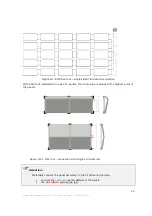
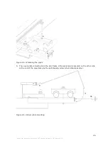
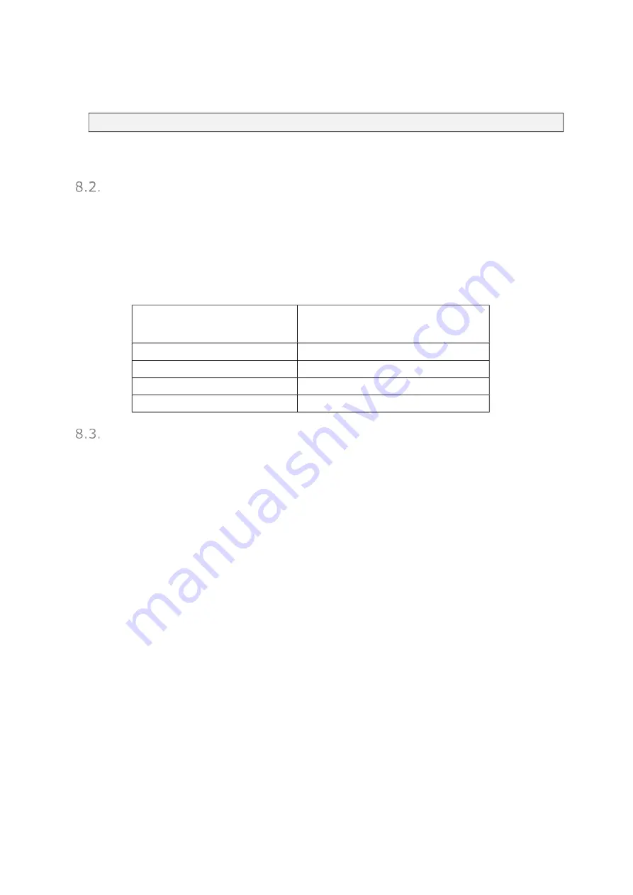
Make sure the air vents remain accessible, also for maintenance
Pipe diameters of source pipes
The pipe diameter is largely dependent on the power of the heat pump. In addition, the total
length of the pipework, the number of bends and the height difference between the heat pump
and the panel field are important. The table below provides a guideline for sizing the pipe
diameters of source pipes. This concerns the minimum diameters of the pipes running to and
from the panel field, including the fittings.
After the junctions in the panel field, pipe diameters can be reduced.
Power heat pump
minimum internal diameter of the
pipes running to and from the panel
field
6 kW to 8kW
26 mm (inside)
8 kW to 15kW
32 mm (inside)
15kW to 28kW
41 mm (inside)
28kW to 50kW
51 mm (inside)
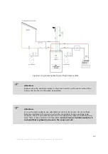
Hydraulic plan
•
See the general hydraulic plan Triple Solar system, Figure 8.3-a
•
Fit a 3 bar pressure relief valve or use the supplied expansion vessel connection group (3 bar
pressure relief valve with automatic air vent).
•
The filter valve (supplied with Nibe heat pumps) must always be placed in front of the
thermostatic mixing valve (Esbe mixing valve) to prevent the valve from becoming dirty.
•
The filter valve (supplied with Nibe heat pumps) with the smaller diameter must be placed in
the cold side of the central heating circuit.
•
Preferably do not place taps between the roof and the expansion vessel. This to avoid mistakes
during maintenance.
•
For larger fields it is wise to place a valve per row so that each row can be vented.

