Herrmidicool
I n s t a l l a t i o n , O p e r a t i o n & M a i n t e n a n c e M a n u a l
4
www.trioniaq.com
I. INTRODUCTION
The Herrmidicool system is an in-duct air/water atomization
system designed to introduce atomized water into the
airstream. The unit uses a native BACnet controller that
responds to an analog 0-5 VDC demand signal to start the
humidification process. An input for proving airflow prior to
starting the system is provided as well as alarm indication.
The touchscreen display allows the operator to interact with
the system. Network communications are available to allow
system monitoring and control.
II. OPERATIONAL CHARACTERISTICS
Upon an increase in demand signal above 20%, the controls
will energize the compressed air solenoid valve. An air
pressure switch will close if sufficient air pressure is present
to allow for proper atomization. When the air pressure switch
contacts close, the water solenoid valve will energize and
atomization will begin. Each nozzle is equipped with a clean
out pin that helps keep the water orifice clear of mineral build-
up each time the nozzle is cycled. Periodically, the controls
will de-energize the water solenoid valve in order to actuate
the clean-out pin to keep the water orifice clear. During
operation if the air proving switch contacts open, the system
will stop. If the system on/off switch is opened the system
will stop. See the Controls section for additional details.
Allowable Operating Conditions
Ambient Temperature: 40°-120°F (4°-50°C)
Ambient Relative Humidity: 0% - 90%
Line Voltage: -15% to +10% Nominal
Frequency: 50/60 Hz
Supply Air Pressure: 60-200 psig
Supply Air Quality: Filter clean and dry to 35°F dewpoint.
Supply Water Temperature: 40°-100°F (4°-38°C)
Supply Water Pressure: 50-100 psig
Supply Water TDS less than 50 ppm: Consult Factory
with water analysis and application data prior to selecting
equipment.
NOTE: If units are mounted in outdoor enclosures, conditions
inside enclosure must be maintained as listed above.
III. MOUNTING
The Herrmidicool system consists of two basic components:
the control cabinet and the atomizing-head manifold
assembly. The control cabinet should be mounted so that the
water outlet of the control cabinet is level or below the water
manifold in the air handler. Air vents must be mounted on
any loops necessary to connect the cabinet to the manifolds.
Minimum Cabinet Clearances:
Top: 1” Bottom: 12”
Sides: 2” Front: 4”
32” Working Area Clearance
Hang the cabinet on the wall or unistrut mounting frame.
Two keyhole slots and two additional mounting holes are
provided. Be sure the unit is level and mounted directly
to the wall to wood studs as least 2” thick (or equivalent).
The atomizing head manifolds consisting of air manifolds,
atomizing heads, water manifold and unistrut brackets are to
be located as shown on specific layout drawings with each
job. Typically, a “unistrut” style mounting structure is field
fabricated to support the atomizing manifold.
Manifold Installation:
1. Install the air/water manifolds per the layout drawing
included with this package.
2. Use only copper, plastic or stainless steel piping as
specified in your print package.
3. Keep runs between control cabinets and heads as short
as possible.
4. Piping runs between control cabinets and manifolds
should be as direct as possible. If loops are unavoidable,
automatic air vents must be supplied and installed.
IV. PLUMBING
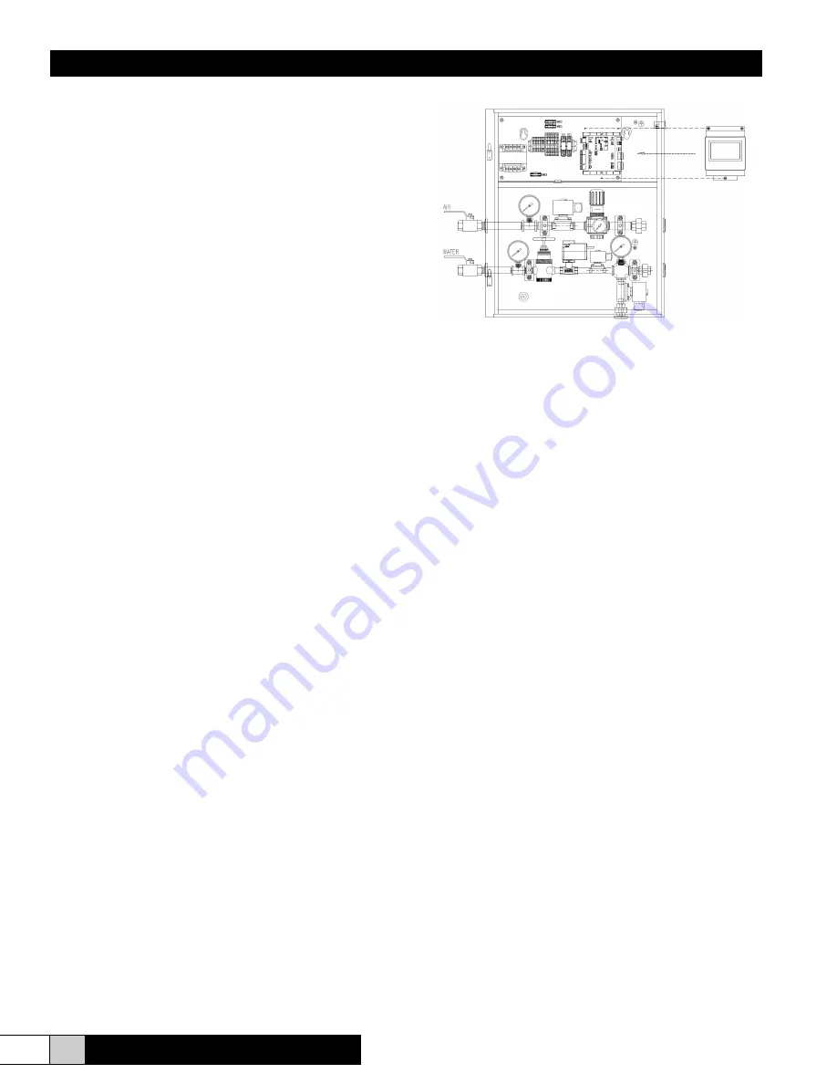
Each cabinet has an air inlet, water inlet, air outlet(s), water
outlet(s) and a drain. All air connections are ½” and all water
connections, including drain, are ½”.
1. Drain loop must extend 3” above highest location of
heads or water outlet port on cabinet. This loop allows water
pressure to be relieved on system shutdown.
2. Piping from control cabinet to manifolds without draining
should be ¾” for the air and ½” for the water piping unless
otherwise shown on your job specific drawings provided for
your project.


