Herrmidicool
I n s t a l l a t i o n , O p e r a t i o n & M a i n t e n a n c e M a n u a l
6
www.trioniaq.com
(0-5 VDC). When the demand is greater than 20% (1 VDC),
the system will enable the compressed air solenoid valve;
starting the system. On any screen, the user may return
to the HOME screen by touching the house pictured in the
upper left of the screen.
The STATUS, PARAMETERS, & ALARM, screens are
described below.
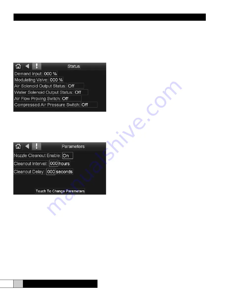
The STATUS screen (shown above) displays the state of
the inputs and outputs. The demand Input displays the
percentage of demand being supplied to the controller input.
This screen will show the user the status of the inputs and
ouputs.
The PARAMETERS screen (shown above) allows the user
to change the way the system works regarding nozzle
cleanout. If enabled, at the interval set by the parameter,
the water solenoid will de-energize for the duration set by
the Cleanout Duration parameter. If Nozzle Cleanout is
disabled, the system will operate continuously whenever
there is a demand input.
The ALARM screen (not shown) allows the user to check the
status of active alarms and alarm history. Whenever the red
exclamation point is shown on the screen, there is an active
alarm. If the exclamation point is gray, there are no active
alarms. The user may go to the alarm screen at any time
to check the history of alarms that have returned to normal
conditions.
There are two possible alarm conditions that may present
themselves during operation. They are the Air Proving Switch
and the Compressed Air Pressure Switch. After a demand
is present and the unit attempts to start, if either of these two
switch inputs fails to close, the unit will shut down and an
alarm will be present. Once the condition is corrected, the
unit will commence normal operation automatically.
The SETUP and MODULE STATUS screens are gateways to
lower level settings that should only be adjusted by a system
administrator. CHANGING SOME OF THESE SETTINGS
MAY RENDER THE FACTORY WARRANTY VOID
When touching SETUP or MODULE STATUS, the
administrator will be prompted for a password. Enter 2222 to
log in to the controller. Network settings, date and time may
be adjusted via the SETUP screen. The MODULE STATUS
screen should not be used without the direction of the factory.
The CLOCKSET screen allows the date, time, and daylight
savings time details to be programmed into the controller.
Unless the date & time are set, the controller will report
incorrectly on the ALARM screen.
VII. START-UP CHECKLIST
This Check List is intended to highlight critical installation
points. A poor installation frequently results in start-up
difficulties, and always results in less than ideal operation of
the humidifier.
1. Insure all valves and valve cocks through the system
(especially at every head) are shut-off.
2. Electric power is connected to the control cabinet per the
diagram.
3. All sensors, airflow switches and external inputs are
connected to the cabinet.
4. Air compressor is primed, oiled and air supply is
connected to the cabinet.
5. Air supply line has been purged and blown down to
remove any installation dirt.
6. Air supply line has been charged, leak tested and has a
minimum of 60 psi pressure to the cabinet.
7. Water supply is connected to the cabinet and has been
purged and blown down to remove installation dirt.
8. Water supply is charged and leak tested and has a
minimum of 50 psi pressure at the cabinet.
9. Drain loop has been connected to the bottom of the
cabinet and has been plumbed to an open drain.
10. Drain piping is installed with a loop a minimum of 3”
above atomizing heads and all piping after the cabinet.
11. All water piping from the cabinet to the manifolds is level
and without loops or automatic float type air vents have
been installed at high points to remove trapped air.
12. Air handler is completely operational and has been
balanced.
13. All air and water lines at the ends of the manifolds have
been terminated with hose bibs.
14. Mist eliminators, if used, have been installed properly
over drain pan that is trapped.


