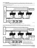
FIGURE 4. WIRING DIAGRAM
(CONNECTED TO 24V POWER USING COMPATIBLE FACP WITH “SOUNDER BASE STANDBY POWER MONITORING” ENABLED)
FIGURE 5. WIRING DIAGRAM (CONNECTED TO NAC OR 24V POWER; OPTIONAL EOL DEVICES FOR CONSTANT SUPERVISION)
(+) SLC
(–) SLC
(–) CONSTANT POWER
(–) NAC
(+) CONSTANT POWER
(+) NAC
U
.L.
LISTED COMP
ATIBLE
CONTR
OL P
ANEL
OPTIONAL REMOTE
ANNUNCIATOR MODEL
TR-RA100Z
CLASS A OPTIONAL WIRING
FIRST
SOUNDER
BASE
SECOND
SOUNDER
BASE
LAST
SOUNDER
BASE
N
OT
USED
SLC +
EXT –
EXT +
RA
SLC –
N
OT
USED
SLC +
EXT –
EXT +
RA
SLC –
N
OT
USED
SLC +
EXT –
EXT +
RA
SLC –
(+)
(+)
(+)
(–)
(–)
(–)
EOL
A SEPARATE SYNCHRONIZATION MODULE MAY BE USED TO PROVIDE
THE SYNCHRONIZATION PULSES (SEE FIGURE 6)
/
/
HORN
HORN
HORN/STROBE
FIRST
SOUNDER
BASE
SECOND
SOUNDER
BASE
LAST
SOUNDER
BASE
N
OT
USED
SLC +
EXT –
EXT +
RA
SLC –
N
OT
USED
SLC +
EXT –
EXT +
RA
SLC –
N
OT
USED
SLC +
EXT –
EXT +
RA
SLC –
(+) SLC
(–) SLC
(–) NAC OR CONSTANT POWER*
(+) NAC OR CONSTANT POWER*
(+) NAC
(–) NAC
OPTIONAL REMOTE
ANNUNCIATOR MODEL
TR-RA100Z
(+)
(+)
(+)
EOL
A SEPARATE SYNCHRONIZATION MODULE MAY BE
USED TO PROVIDE THE SYNCHRONIZATION PULSES
HORN
HORN/STROBE
UL LISTED COMP
ATIBLE
CONTR
OL P
ANEL
UL LISTED 24V PO
WER SUPPL
Y
*WHEN USING 24V CONSTANT POWER
(AUX POWER), ADDITIONAL POWER
SUPERVISION RELAYS AND MODULES WILL
BE REQUIRED FOR PROVIDING SUPERVISION
WHEN THE SOUNDER BASES ARE INACTIVE.
CLASS A OPTIONAL WIRING
(–)
(–)
(–)
/
/
EOL
/
/
HORN
C0474TRG-24
C0474TRG-25
NOTE: Only use this wiring diagram when connecting to 24VDC power using a FACP listed in the table on page 1. Please consult your FACP manufacturer for
panel-specific wiring configurations and special cases.
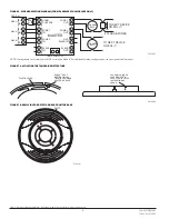
Additional Audible Visible devices may be connected to the same power supply or the the NAC output of the Fire Alarm Control Panel (FACP) to provide a syn-
chronized communication of the alarm signal.
(SEE FIGURE 6)
NOTE: Only use this wiring diagram when connecting to a NAC or a 24V power supply that does not support “sounder base standby power monitoring”
(see page 1).
3
I56-4151TRG-005
4/22/2021


