18
TRI TOOL INC.
92-1482 Rev. 190410
5.2 GETTING STARTED
1. Select the recommended jaw blocks and/or ramp set for the pipe size to be
machined. Refer to section 9, Jaw Blocks and Ramps.
2. Install the mandrel assembly into the pipe.
CAUTION
CAUTION: To avoid cutting the jaw blocks, install the mandrel
beyond the location of the final end preparation.
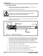
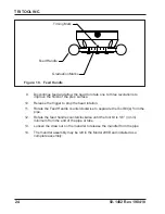
3. Tighten the draw nut refer to (Fig. 4) to force the jaw blocks out to the inside
diameter of the pipe or tube.
PIPE
JAW BLOCK
MANDREL
ASSEMBLY
DRAW NUT
FINAL PREP
LOCATION
Figure: 4. Location of the Draw Nut
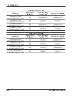
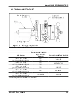
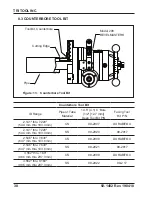
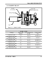
4. Select the tool bit(s) required to machine the pipe to the configuration desired.
Use of dull or improperly designed tool bits or tool bits not manufactured by
TRI TOOL INC. may result in poor performance and may constitute abuse of
this machine and therefore voids the TRI TOOL INC. factory warranty.
5. When performing any multiple machining operation such as facing, beveling,
and/or counterboring, install the counterbore tool bit to ‘lead’ the bevel tool bit.
6. Attach the tool holders to the Model 208B.
7. Insert the tool bit(s) into the slot(s) in the tool holder(s).
8. The cutting edge of the tool bit(s) must be located on the radial centerline.
9. Ensure that none of the tool bits are installed backwards.
10. Tighten the set screws to secure the tool bit(s) to the tool holder(s).
Содержание BEVEL MASTER 208B
Страница 1: ...92 1482 Rev 190410 Model 208B BEVELMASTER ...
Страница 54: ...52 TRI TOOL INC 92 1482 Rev 190410 MOTOR ASSEMBLY HYDRAULIC P N 56 0101 5 3 1 2 4 10 9 6 8 7 ...
Страница 57: ...This Page is Intentionally Left Blank ...
Страница 58: ......


