


Instruction manual TREJON OPTIMAL UPX plough (2010)
20
Stability.
The machine must not be operated with a tool carrier that does not weigh enough over
the front/rear axle, such that the stability of the tool carrier is affected. Mount ballast weights if
necessary, see the tool carrier’s instruction manual.
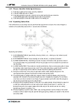
Operating the Machine.
Take great care when working on uneven ground conditions, close to
ditches and fences, look out for hidden dangers and adapt your working rate.
Do not reverse with the plough down (the wrong way).
Great care should be observed when working on steep slopes.
Hold onto the steering wheel tightly if the tool carrier should overturn.
Operating at Night.
The work area must be illuminated when working in the dark.
Driver.
Operators who are tired, intoxicated, drugged or under the influence in any other way so
that they cannot control their movements must not use the machine.
The machine may only be operated by one person sitting in the tool carrier, no passengers
are allowed.
It is prohibited for people without authorisation to use the machine.
Personal protective equipment.
Protective equipment such as helmets, protective goggles,
protective shoes and gloves are recommended for personnel during assembly, operation,
adjustment and maintenance.
Protective Cab.
The machine should only be driven by a tractor equipped with an approved
protective cab. Keep doors and windows close while working.
All moving parts, including engine, must be stationary and the handbrake applied before the
operator leaves the cab. When travelling on ice-covered water the roof hatch must be kept open.
When travelling on ice-covered water the roof hatch must be kept open.
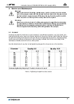
Maintenance.
Inspect, adjust and maintain the machine according to the directions.
Regular Inspection.
Inspect the entire machine regularly. Locate any loose, worn and damaged
components and leaks.
Safety During Maintenance and Service.
The machine must be standing on firm, even ground
for maintenance and adjustment. The engine must be shut off, all moving parts stationary,
the machine lowered to the ground and the handbrake applied during all cleaning, inspection,
adjustment, maintenance and repair work.
Clean the machine thoroughly before repair and storage.
Bearing and hydraulic components should not the cleaned with high-pressure jets.
If excessively high pressure is used for general cleaning, this may damage the paint.
After cleaning, the machine must be lubricated according to the lubrication schedule and a short
test run carried out.
Vibration.
If any vibration should occur in the machine, it must be shut down immediately and
the cause located. Change any damaged parts.
Emergencies
. Stop the machine immediately if it should hit an obstruction. Shut off the engine,
remove the key, check for and repair any damage before recommencing work.
Make yourself aware of how emergency stops work on the tool carrier, and be prepared for how
they work in an emergency situation.
Содержание OPTIMAL UPX Series
Страница 2: ...Instruction manual TREJON OPTIMAL UPX plough 2010 2...
Страница 39: ...Instruction manual TREJON OPTIMAL UPX plough 2010 39 7 Notes...
Страница 41: ...Instruction manual TREJON OPTIMAL UPX plough 2010 41...
Страница 42: ...Instruction manual TREJON OPTIMAL UPX plough 2010 42...
Страница 44: ...TREJON F RS LJNINGS AB F retagsv gen 9 SE 911 35 V NN SBY SWEDEN Tel 46 0 935 39 900 Web trejon se...