The gas/liquid mixture is separated in a cylindrical tank (separator), the gas is
vented through the top mounted discharge flange of the separator and the liquid
is collected at the bottom of the separator ready to be returned to the vacuum
pump.
During the suction and compression cycle of the vacuum pump, all the energy is
transformed into heat energy and almost all of it is absorbed by the ser vice liquid.
Therefore the liquid must be cooled prior to be returned to the pump, either with
a heat exchanger (total recover y system) or with the addition of cool make-up liq-
uid (par tial recover y system).
The
FULL RECOVERY
system (see fig. 32 and legend) does not require an appre-
ciable flow of make-up from an external source but only the necessar y amount to
compensate for the liquid lost due to evaporation, with the discharged gases.
The heat exchanger sizing should be based on using a minimum amount of cool-
ing liquid (usually water) to keep the ser vice liquid at the ideal temperature for the
best efficiency of the vacuum pump. Remember the higher the temperature of the
ser vice liquid the higher the losses in pump capacity and maximum vacuum see
section 17.
This system is par ticular suitable where the ser vice liquid and the condensed
gases cannot be discharged to the environment, either for pollution reasons or
because the fluids are too valuable.
The
PARTIAL RECOVERY
system (see fig. 32a and legend) requires a constant
flow of cold make-up liquid from an external source. This liquid must be of the
same nature as the ser vice liquid being used by the pump. The mixture of the
make-up and the ser vice liquid being discharged by the pump, will have a constant
temperature when enters the vacuum pump ser vice liquid connection.
The same amount of ser vice liquid taken from the outside source must be over-
flowed through the separator over flow connection situated at the pump shaft cen-
terline. This system is utilized in many applications for conditions where there is
intermittent use, or low vacuum levels, or there is no danger of pollution and the
liquid can easily be drained.
Fur thermore, this may prove to be the only alternative to the total recover y sys-
tem for those installations where the cooling liquid is not available or it is too
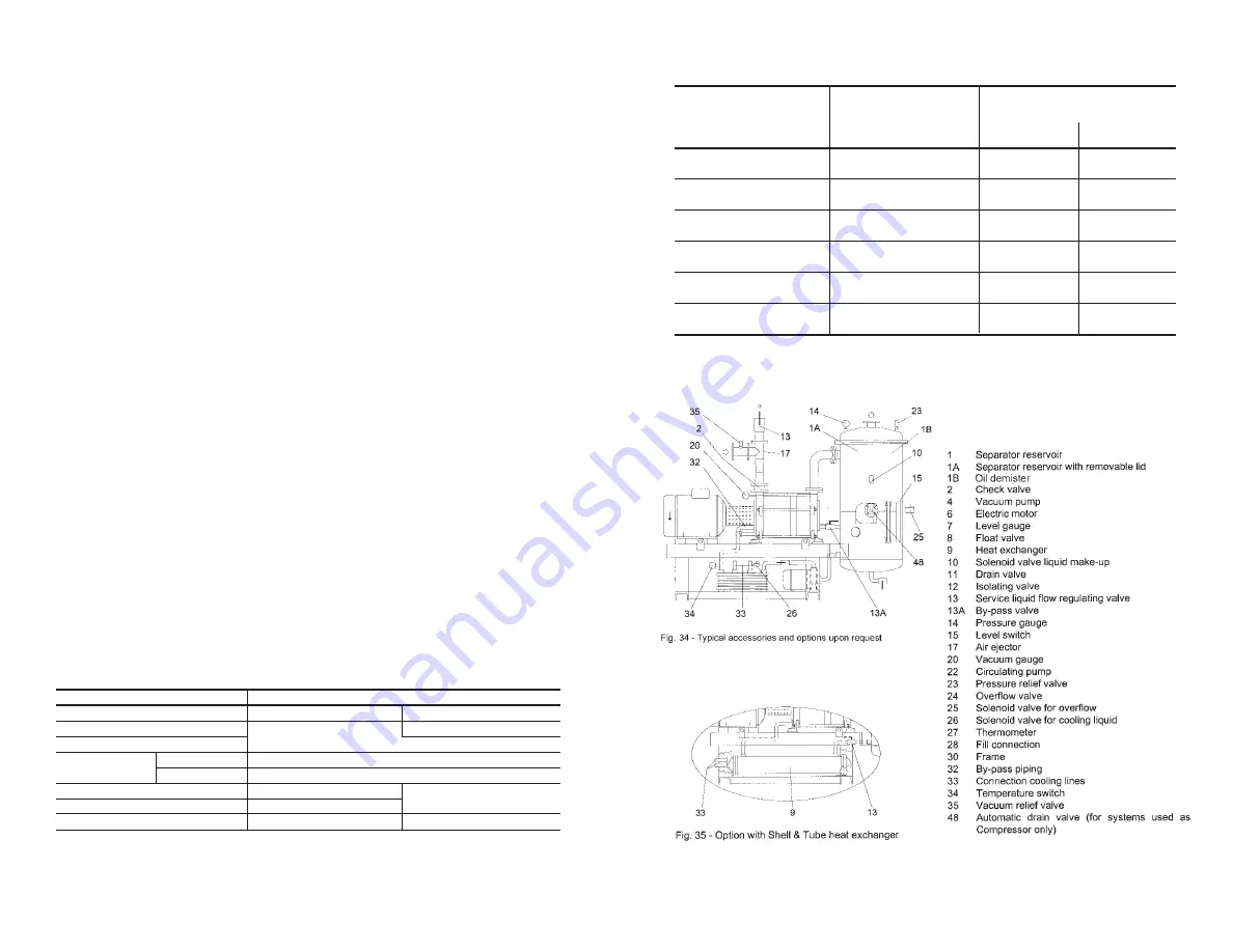
warm. Numerous accessories are available to meet the customers’ requests and
suitable for the installation, process and maintenance. For materials of con-
struction and some engineering data see table 11 and 12.
Table 11 - STANDARD MATERIALS FOR “WATER SEALED” SYSTEMS
COMPONENT
MATERIAL DESIGN
Vacuum pump
GH - F - RA - RZ
A3
Separator reser voir
Carbon steel
AISI 316 SS
Baseplate
Heat
Plates
Carbon Steel
Exchanger
Gaskets
Nitrile rubber / Viton
Piping
Carbon steel
AISI 316 SS
Valves - Thermometer
Brass
Level gauge
Polycarbonate
“Pirex” Glass
For vacuum pump materials (GH - F - RA - RZ - A3) see section 4.
Table 12 - GENERAL AND NOT BINDING ENGINEERING DETAILS
FOR “WATER SEALED” and “OIL SEALED (DynaSeal™)” SYSTEMS
WATER SEALED
2
5HP
300
450
OIL SEALED
2 poles / 60 Hz
WATER SEALED
3
5HP
400
800
OIL SEALED
4 poles / 60 Hz
WATER SEALED
4
10HP
1000
1000
OIL SEALED
4 poles / 60 Hz
WATER SEALED
5
20HP
1200
1500
OIL SEALED
4 poles / 60 Hz
WATER SEALED
6
40HP
1800
2000
OIL SEALED
4 poles / 60 Hz
WATER SEALED
7
60HP
2500
3500
OIL SEALED
6 poles / 60 Hz
EXAMPLE OF “WATER SEALED” SYSTEM General Schematic and Accessories or Options
– 42 –
– 41 –
PACKAGE
SERIES
Motor Size
Dry weight lbs.
WATER
SEALED
OIL SEALED
(DynaSeal
TM)
)
LEGEND


