background image


111 
This document is intended for Public Distribution                         
19473 Fraser Way, 

Pitt Meadows, B.C. Canada V3Y  2V4


Appendix E 

E-1 

TR-Multi Series


Tranzeo Wireless Technologies 

Appendix E: Channel Allocations  


The following tables list the channel numbers and center frequencies used for 
802.11a and 802.11b/g. Note that while all of these frequencies are in the 
unlicensed ISM and U-NII bands, not all channels are available in all countries. 
Many regions impose restrictions on output power as well as indoor and outdoor 
use on some channels. These regulations are rapidly changing, so always check 
your local regulations before transmitting. 
 
These tables show the center frequency for each channel. Channels are 22 MHz 
wide in 802.11b/g and 20 MHz wide in 802.11a. 


802.11b/g 

Channel 

Center Frequency  

(GHz) 

Channel 

Center Frequency 

(GHz) 

1 2.412 8 2.447 
2 2.417 9 2.452 

3 2.422 10 2.457 

4 2.427 11 2.462 

5 2.432 12 2.467 

6 2.437 13 2.472 

7 2.442 14 2.484 

802.11a 

Channel 

Center Frequency  

(GHz) 

Channel 

Center Frequency 

(GHz) 

34 5.170 52 5.260 
36 5.180 56 5.280 

38 5.190 60 5.300 

40 5.200 64 5.320 

42  5.210 149 5.745 

44  5.220 153 5.765 

46  5.230 157 5.785 

48  5.240 161 5.805 

Содержание TR-Multi-2

Страница 1: ...TR Multi Series Revision 1 1 Firmware 2 10 Date 7 06 06 Tranzeo TR Multi Series User Guide ...

Страница 2: ...1 0 June 9 2006 Version 1 1 July 11 2006 Tranzeo Wireless Technologies Inc 19473 Fraser Way Pitt Meadows BC Canada V3Y 2V4 Toll Free Number 1 866 872 6936 Technical Support 1 888 460 6366 General Inquiries info tranzeo com Local Number 1 604 460 6002 Sales sales tranzeo com Fax Number 1 604 460 6005 Technical Support support tranzeo com ...

Страница 3: ... use the device For safety reasons people should not work in a situation where RF exposure limits could be exceeded To prevent this situation the users should consider the following rules Install the antenna so that there is a minimum of 59 cm 23 23 in of distance between the antenna and people Do not turn on power to the device while installing the antenna Do not connect the antenna while the dev...

Страница 4: ...he circuit before attaching the wire Use the Tranzeo Power over Ethernet POE adapter only with approved Tranzeo models Never install radio equipment surge suppressors or lightning protection during a storm Safety Instructions Lightning Protection The key to lightning protection is to provide a harmless route for lightning to reach ground The system should not be designed to attract lightning nor c...

Страница 5: ...upply 2 2 Installing the Ethernet Cable 2 3 Mounting the Radio 2 5 Grounding the Antenna 2 5 Connecting the Radio 2 6 Best Practices 2 7 Chapter 3 Configuration 3 1 Connecting to the Radio 3 1 Changing the IP Address Windows XP 3 1 Changing the IP Address Using the Tranzeo Locator 3 2 Login into the Configuration Interface 3 3 Information Page 3 4 CPE Setup Menu 3 5 Wireless Settings 3 5 Administr...

Страница 6: ... Router Mode 3 15 DHCP Configuration 3 17 IP Routing 3 18 Quality of Service Configuration QoS 3 19 Port Forwarding 3 20 Port Filtering 3 21 Appendix A Grounding and Lightning Protection Information A 1 Appendix B Product Specification B 1 Appendix C Protocol List C 1 Appendix D Common TCP Ports D 1 Appendix E Channel Allocations E 1 Appendix F Quality of Service Configuration QoS F 1 Appendix G W...

Страница 7: ...cker installs where they can be configured in either 2 4 GHz or 5 GHz frequency eliminating the need for two types of radios The TR Multi 2 radios come with a built in antenna The TR Multi N radios do not include an antenna but have an interface for external antennas Product Kit The TR Multi Series product kit contains the items shown below If any item is missing or damaged contact your local deal...

Страница 8: ...he back of the TR Multi Series radio as shown in the picture LED Panel Indicators Note Color of the LED panel indicators may vary Label Color Indicators Power Red On Powered on Off No power LAN Green On Ethernet link Flashing Ethernet traffic Off No Ethernet link Radio Amber On Radio link Flashing Radio activity Off No radio link LED Panel indicators MAC address Ethernet ports Serial number Studs ...

Страница 9: ...Tools Required To install your TR Multi Series radio you will need the following tools 1 2 wrench x 1 3 8 wrench x 1 3 4 wrench x 1 Cat 5 cable stripper x 1 Cat 5 cable to connect the radio to the POE adapter RJ 45 patch cable RJ 45 crimper x 1 RJ 45 connectors x 4 6 green grounding wire Site Selection Determine the location of the radio before installation Proper placement of the device is critic...

Страница 10: ...s polarization will be horizontal or vertical before installation The TR Multi Series radios can be used in either polarity The Ethernet boot cover should always be placed so that the cable runs toward the ground for maximum environmental protection Power Supply Only use a power adapter approved for use with the TR Multi Series radio Otherwise the product may be damaged and will not be covered by ...

Страница 11: ...ack over the strain relief and insert the Cat 5 cable through it Wire the cable following the EIA TIA T568B standard and attach the RJ 45 connectors to each end of the cable See Appendix G Wiring Standard Step 1 Insert the strain relief without the cap nut into the port opening of the boot cover Step 4 If you purchased the device with a dual port cover repeat steps 1 2 and 3 for the second port IM...

Страница 12: ...the gasket with the adhesive side facing up over the 4 studs around the port of the radio Flatten the gasket ensuring there are no gaps Remove the backing Step 8 Make sure the cap nut of the strain relief is tightened properly to ensure a weather proof seal IMPORTANT Hand tighten only Do not over tighten as you may damage the weather tight seal of the strain relief Step 6 Plug the Cat 5 cable inse...

Страница 13: ...enough to prevent any movement Step 10 Fit the radio to the mounting bracket Secure the radio with keps nuts IMPORTANT The strain relief must be always facing the ground Grounding the Antenna Step 11 Using a 6 green grounding wire connect the grounding lug on the radio to a proper ground See Appendix A Grounding and Lighting Protection Information IMPORTANT This device must be grounded Connect the...

Страница 14: ...o a hub or switch a crossover cable may be required IMPORTANT Use the power adapter supplied with the radio Otherwise it may be damaged Step 12 Connect the Cat 5 cable from the radio into the RJ 45 jack marked CPE on the POE adapter The POE adapter is not weather proof and should be installed indoors Step 13 Connect the power adapter to the POE adapter and plug the other end to an outlet The POE a...

Страница 15: ...g pole This helps to insulate the cable from any air surges Keep all runs as straight as possible Never put a loop into the cables Test all grounds to ensure that you are using a proper ground If using an electrical socket for ground use a socket tester such as Radio Shack 22 141 Keep a copy of the National Electrical Code Guide at hand and follow its recommendations If you are in doubt about the ...

Страница 16: ...pret the information displayed in the interface Connecting to the Radio Before accessing the configuration interface you have to change the network connection settings in your computer to be on the same subnet as the radio Changing the IP Address Windows XP 1 In your computer open Control Panel Network Connections Local Area Connection 2 In Local Area Connection Status General click Properties 3 I...

Страница 17: ...e the IP address for your device Note The Locator cannot locate radios through routers The Tranzeo Locator displays the following options Find the latest version of the Tranzeo Locator at www tranzeo com under Tranzeo Support Support Files Radio Utilities Scan Locates Tranzeo radios connected to the network A yellow icon appears before the name when the radio is not in the same subnet Configure Us...

Страница 18: ... if you re a first time user follow the instructions below 4 Click OK You will then access the configuration interface If you re a first time user 1 Enter the default username admin and the default password default 2 In the Password Set Reset window change the Administration and Recovery passwords They cannot be left as default and must be different from each other You can change the usernames too...

Страница 19: ...ranzeo Wireless Technologies Information Page This is the first window of the configuration interface It shows the main menu and information about the device settings like wireless network and security settings The menu is divided in four sections Setup Menu Security Status Network Each section contains navigation links to the configuration windows ...

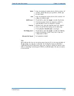
Страница 20: ...d Clients will connect to the secondary access point when the primary is unavailable Band The radio frequency range in which the radio operates 2 4 or 5 8 GHz TX Rate The transmission speed at which the radio communicates with the access point Note Setting this rate below the maximum possible does not limit bandwidth and often has a negative impact on the operation of your network RTS Threshold Th...

Страница 21: ...the antenna used This information must be set by the installer at the time of installation Preamble Select type Long uses long preamble only Auto recommended tries short preamble first then long ACK Timeout Tuning The time that the device waits for an acknowledgment from the access point accepting the transmission before re attempting to send the data This is an offset from the ACK timing set by t...

Страница 22: ...o factory defaults including passwords Reboot Restarts the system without changing settings Rollback To undo the most recent change Device Name It is the network name of the device This name appears in the Locator and on the Tranzeo stations list User Name This is the login username Password Enter a new password if you want to change it Confirm Password Re type the new password Extended Wireless I...

Страница 23: ...dow you can define WEP parameters WEP provides security by encrypting data so that it s protected when transmitted from one point to another Enabled Check to turn on WEP security protocol Authentication Select your system to be open or shared Open is always recommended Key Length This is the level of encryption Note that 64 bit is referred to as 40 bit on some systems Default Key Select the defaul...

Страница 24: ...WPA parameters WPA provides a higher level of security enhancing the security features of WEP Enabled Check to turn on WPA Cipher Type Select the level of encryption PSK Enter your PSK password Authentication Ensures that only authorized network users can access the network Enter the information about the RADIUS server from your Internet Service Provider Update Interval This is the interval at whi...

Страница 25: ...ied in this section AP List This window displays information about the access points associated with the CPE and the connection statistics You can set an access point s SSID as your primary SSID by clicking on the MAC address when it s displayed as a link This will automatically reboot the radio ARP Table This table lists the devices that have communicated with your device via TCP There should be ...

Страница 26: ...lues are useful to ISPs and other users The INT internal statistics are intended for use by Tranzeo Wireless Technical Support You can click onto each speed level and see how the traffic breaks down In the TX statistics there should little to no Tries at Series 2 3 or 4 The radio will try to send a packet 4 times at Series 1 and then will try the next series 4 times In the RX statistics you should...

Страница 27: ...mal operating environment In the TX statistics there should be little to no Retransmits at Series 2 3 or 4 Life Statistics are reset on each reboot Ethernet Statistics In this window excessive collisions are usually a sign that the radio and the device it is linked to are not on the same duplex settings One is at full while the other is at half Try locking both to the same values Collisions do nor...

Страница 28: ... do not allow infinite refreshes of a page through scripts so this window may stop updating If it does simply change the refresh rate to another value to restart the process Select Refresh Rate Set the time for automatic refreshes Net Pages This is the memory used for data transmission Memory This is the total memory of the system Stack This section displays the memory used and available for each ...

Страница 29: ...he MAC address of the device you have connected to the network This is useful when you change your device and don t want to register a new MAC address or when dealing with some PPPoE and Radius implementations When the device is cloning a MAC address it can only be managed from the LAN side To clone a MAC address check the MAC Address box and enter the MAC address in the field Cloning into Uncheck...

Страница 30: ...it MTU refers to the size of the largest packet that the router can pass The default value is 1500 bytes If PPPoE is used you should change the MTU to match the PPPoE server typically 1492 bytes Allow Pinging Enables ping responses on WAN interface Allow Access to Web Server Allows access from WAN interface or change the port the WAN server responds to web server requests Note Access to web server...

Страница 31: ...or place a switch in line WAN Enter the information related to the WAN interface IP Address Subnet Mask Gateway DNS1 DNS2 and Domain Name Routing Enables NAT QoS and Static Routes NAT should always be enabled when using private addressing Click on QoS or Static Routes to configure Port Management Check the box and click Apply to enable port filtering and port forwarding Click on any item to open t...

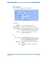
Страница 32: ...ect Other to use a different gateway Lease Time Indicates the expiration time for the IP address assigned by the DHCP server Address Starting from Indicates the first address in the DHCP pool Number of Addresses Indicates the number of addresses in the DHCP pool Server IP Address Select WAN Assigned to use the DNS server IP addresses assigned on the WAN side To use different DNS servers select Sta...

Страница 33: ...k that the packets will be attempting to access Subnet Mask Specifies the part of the destination IP that represents the network address and the part that represents the host address Note 255 255 255 255 represents only the host entered in the Destination IP field Gateway Indicates the next hop if this route is used A gateway of 0 0 0 0 means there is no next hop and the IP address matched is dire...

Страница 34: ...ally classifies traffic and gives priority to certain applications Applications such as VOIP and gaming are automatically given priority Enabled Check to activate a rule Priority Enter the priority of the rule between 0 and 255 Name Enter the name of the rule here Protocol Enter the protocol number here Common options are 0 for ANY 1 for ICMP 6 for TCP and 17 for UDP See Appendix C for Protocol Li...

Страница 35: ...dow you can create edit delete and manage rules for port forwarding A list of port forwarding rules appears at the bottom Enable Port Forwarding Click to apply rules from the Rules list Forward Rule ID Enter the rule ID here to retrieve its information Enabled Disabled Activate or deactivate the selected rule External Port Enter the port to which requests will be forwarded Internal Port Enter your...

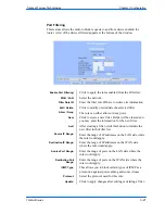
Страница 36: ... of IP addresses on the WAN side where the rule would apply Source Port Range Enter the range of ports on the LAN side where the rule would apply Destination Port Range Enter the range of ports on the WAN side where the rule would apply ICMP Type This allows you to block certain types of ICMP as a prevention against port scanning and some viruses Protocol Select the protocol used for this rule Upd...

Страница 37: ... is coiling the LMR or Cat 5 bad The myth is that lighting follows the path of least resistance It actually follows the path of least impedance Coiling cables creates an air wound transformer which lowers the impedance This means you are in fact making your radios a more appealing target for surges What standard does Tranzeo Wireless equipment meet This radio exceeds International Standard IEC 610...

Страница 38: ...evice This radio must be grounded at the pole and at the POE This is because the radio is between the exterior antenna and the POE ground See the examples below Grounded Radio A grounded radio causes the surge to pass directly to ground bypassing the radio Ungrounded Radio An ungrounded radio causes the surge to pass through the radio In this case the radio most likely will be damaged ...

Страница 39: ...ogies Grounded POE In this case the surge will be picked up by the Cat 5 cable and since the POE is grounded the route for the surge is through the POE to ground Ungrounded POE In this case the surge will be picked up by the Cat 5 cable and since the POE is not grounded the route for the surge is through the radio to the antenna and out through the building ...

Страница 40: ...Vertical TR Multi N N Connector 105 165 N A N A TR Multi 2 16dBi 2 4 GHz 20dBi 5 GHz Panel 182 285 18 2 2 4 GHz 10 5 5 GHz 18 2 2 4 GHz 10 5 5 GHz Management Remote Configuration Based on IP Address Device Management Windows Utility Web Based Management Protocol Supported TCP IP Security 40 bits and 128 bits WEP encryption Access Control address filter MAC WPA encryption Ethernet Connector 10 100 ...

Страница 41: ...tocol 47 GRE General Routing Encapsulation 48 MHRP Mobile Host Routing Protocol 49 BNA BNA 50 ESP Encap Security Payload for IPv6 Dec Keyword Protocol 51 AH Authentication Header for IPv6 52 I NLSP Integrated Net Layer Security 53 SWIPE IP with Encryption 54 NARP NBMA Address Resolution 55 MOBILE IP Mobility 56 TLSP Transport Layer Security using Kryptonet key management 57 SKIP SKIP 58 IPv6 ICMP ...

Страница 42: ...5 L2TP Layer Two Tunneling Protocol 116 DDX D II Data Exchange DDX 111 IPX in IP IPX in IP 117 IATP Interactive Agent Transfer 118 STP Schedule Transfer Protocol 119 SRP SpectraLink Radio Protocol 120 UTI UTI Dec Keyword Protocol 121 SMP Simple Message Protocol 122 SM SM 123 PTP Performance Transparency 124 ISSIS ISIS over IPv4 125 FIRE 126 CRTP Combat Radio Transport 127 CRUDP Combat Radio User D...

Страница 43: ... Keyword Port Description ECHO 7 Echo SYSTAT 11 Active Users QOTD 17 Quote of the day MSP 18 Message Send Protocol FTP DATA 20 File Transfer Data Channel FTP 21 File Transfer Control TELNET 23 Telnet SMTP 25 Simple Mail Transfer NAME 42 TCP Nameserver BOOTPS 67 Bootstrap Protocol Server BOOTPC 68 Bootstrap Protocol Client TFTP 69 Trivial File Transfer WWW 80 World Wide Web KERBEROS 88 Kerberos POP...

Страница 44: ...wer as well as indoor and outdoor use on some channels These regulations are rapidly changing so always check your local regulations before transmitting These tables show the center frequency for each channel Channels are 22 MHz wide in 802 11b g and 20 MHz wide in 802 11a 802 11b g Channel Center Frequency GHz Channel Center Frequency GHz 1 2 412 8 2 447 2 2 417 9 2 452 3 2 422 10 2 457 4 2 427 1...

Страница 45: ... scenario with Tranzeo s QoS enabled the voice quality remains consistently high with an MOS of 4 4 and maintains that level even with multiple FTP streams Automatic Traffic Classification Tranzeo software has the capability of continually monitoring and classifying traffic on the Internet connection and dynamically adjusting the way individual streams are handled at any point in time This enables...

Страница 46: ...as email or file transfers are de prioritized Dynamic Fragmentation Automatic Classification Rate Matching High Priority High Priority High Priority High Priority Internet Non latency sensitive traffic Low priority or excess traffic Queue Queue Intelligent Stream Handling adjusts the fragment size based on the uplink speed and also stops fragmenting long packets when no latency sensitive traffic i...

Страница 47: ...30 MB 5A PxP 6000 AP QoS 6000 CPE Shaped to 2 MB QoS 6000 CPE VOIP Computer Computer Shaped to 1 MB In this case no user is ever able to draw more than their fair share of the available up stream bandwidth even if the communication is between two stations on the same access points In this case the head end shaper is limiting the incoming demand based on the end user to ensure no user is taking the...

Страница 48: ...zeo Wireless Technologies TIA EIA 568 B is a set of standards for cabling telecommunications products and services Follow these standards as described in the diagram below to wire the Cat 5 cable during installation of the Tranzeo radio see Step 3 in Chapter 2 Hardware Installation Installing the Ethernet Cable Appendix G Wiring Standard ...

Страница 49: ......

Отзывы: