4.24 Fixed Height Stretcher Upper Frame
Chapter 4: Removal, Replacement, and Adjustment Procedures
Page 4 - 78
TranStar® PC-100/PC-200/PC-300/PC-350/PC-400/PC-450/
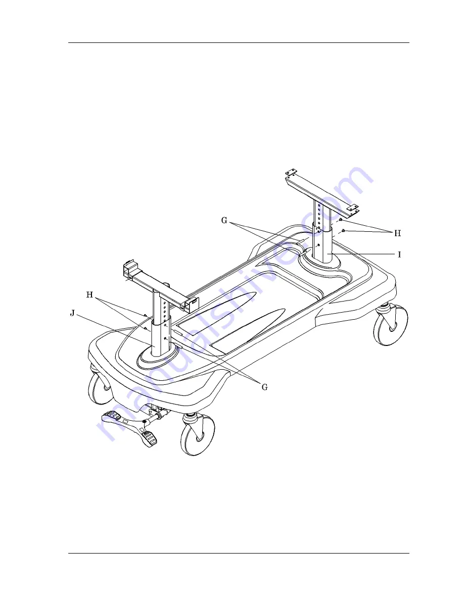
PC-500/PC-550/TR-500/SG-500/OB-450/OB-550/EL-550
Series Stretcher Service Manual (man115re)
4. Install the four height adjustment pins (G) into both the head column (I)
and foot column base weldments (J). The pins should protrude from the
opposite side of base weldments.
5. Using the ¼" Allen™ wrench, install the two screws (H) into the head
column base weldment (I) pins (G) and foot column base weldment (J) pins
(G). The screws should be fully seated on the pins.
Figure 4-39. Fixed Height Stretcher Upper Frame Height Adjustment
Replacement
1. Put the upper frame onto the base assembly. Ensure that the frame is in
position, and the holes align on the head end (B) and foot end weldments
(F) (see figure 4-38 on page 4-77).
m115d107
Содержание EL-550
Страница 2: ......
Страница 509: ...Schematic Wiring Diagram Control Board P N 49603 Back to Chapter 3 ...
Страница 510: ...Schematic Wiring Diagram Electric Stretcher P N 60389 Back to Chapter 3 ...


