Transcell Technology TI-1520 Скачать руководство пользователя страница 6


CONNECTING THE SERIAL I/O DEVICE 

 
The TI-1520 model comes standard with one full duplex RS-232 serial port, designed for connection to a 
computer or a serial printer. The same port may be also used as a simplex, RS-232 port designed for 
connection to a remote display.  


Connection assignments for all serial RS-232 communication terminals on the TI-1520 are shown below.  


RS-232 Terminal (J3) 


Pin No. 

Marking 

Function 


Pin No. 

Marking 

Function 

TXD2 

TXD 


RXD1 

CTS 

RXD2 

RXD 


GND 

Ground 

TXD1 

RTS 


CONFIGURATION 


OVERVIEW 

 
The indicator contains two main configuration menus:  


The Setup (“F”) menu, which configures the indicator to your weigh platform 


The User (“A”) menu, which configures the serial communication port and enables some user 
options 


The Setup and User menus consist of several menu selections, each with its own sub-menu of selections 
or programming procedures. To configure the indicator you must first enter the appropriate menu mode. 
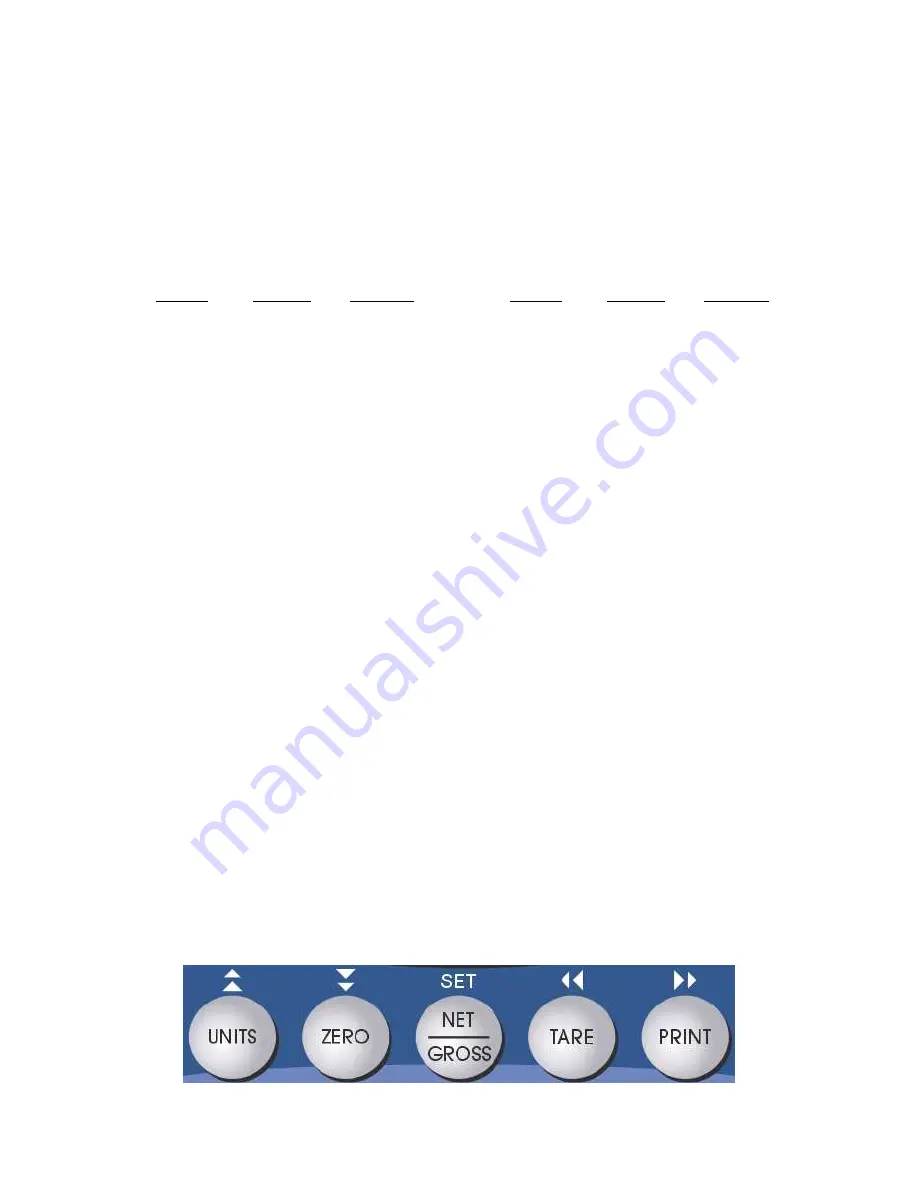
Once  there,  four  of  the  front  panel  keys  become  directional  navigators  to  move  around  in  the  menus, 
and one key is used to save or SET the selections. 


ACCESSING THE MENUS 

 
To access the Setup (“F) menu: 

1.  Power off the indicator. 

2.  Locate the slide switch on the rear cover and move it to the opposite position. 

NOTE: A metal plate held on by two drilled-head screws may conceal the slide switch. 

3.  Power on the indicator.  

The display shows ” F   1” to indicate that you are in Setup Menu mode. 

4.  Use the navigation keys shown in the figure below to move through the menu. 


To access the User (“A) menu: 

1.  Enter the Setup (“F”) menu. 

2.  Use the right or left directional keys shown below to move right or left in the Setup (“F”) menu 

until the indicator shows ” A   1”. 


Содержание TI-1520

Страница 1: ...MODEL TI 1520 Digital Weight Indicator User Manual Revision 1 8 August 3 2012...

Страница 2: ...EW CALIBRATION VALUES F18 12 KEY IN ZERO CALIBRATION VALUE F19 13 KEY IN SPAN CALIBRATION VALUE F20 13 OPERATION 14 DISPLAY 14 KEYBOARD 15 FUNCTION KEYS 15 GENERAL SCALE OPERATION 15 WEIGHING AN ITEM...

Страница 3: ...idential installation This equipment generates uses and can radiate radio frequency energy and if not installed and used in accordance with the instructions may cause harmful interference to radio com...

Страница 4: ...ssible In extreme cases it may be necessary to install surge suppressors line conditioners or even UPS Uninterruptible Power Supplies systems not included Environment Avoid installing the indicator in...

Страница 5: ...o the green load cell input terminal The TI 1520 indicator contains a connection terminal on the main board for connection to the load cell cable Connect your shielded load cell cable not included to...

Страница 6: ...The Setup and User menus consist of several menu selections each with its own sub menu of selections or programming procedures To configure the indicator you must first enter the appropriate menu mode...

Страница 7: ...S This section provides more detailed descriptions of the selections found in the Setup Menu Chart Factory set defaults are shown in bold NA for North America and for Europe NOTE Some selections are s...

Страница 8: ...al point 0 NA 0 0 0 00 0 000 0 0000 00 F14 Units Conversion Allows the lb kg key to be disabled so that an operator cannot accidentally press the key and change the displayed units 0 Disable the Units...

Страница 9: ...0 0 NA 10 F32 Center of Zero Band Selects the range around gross zero within which the scale will display the Center of Zero annunciator Selections are in display divisions d 0 25d US 0 5d F34 Auto Pr...

Страница 10: ...Loads in a pre defined output string print format for the serial port Refer to Appendix B for details 0 Text Print Ticket 1 String Format 1 Condec Demand 2 String Format 2 Condec Continuous 3 Text Pri...

Страница 11: ...alue Increase the flashing digit by pressing the UNITS key Decrease the flashing digit by pressing the ZERO key Pressing the PRINT key or the TARE key will change the position of the flashing digit 4...

Страница 12: ...3 Use the four directional keys to adjust the displayed value to the actual date value Increase the flashing digit by pressing the UNITS key Decrease the flashing digit by pressing the ZERO key Press...

Страница 13: ...troubleshoot setup problems 2 After making sure that there are no test weights on the platform press the ZERO key again to zero out the displayed value 3 Press the NET GROSS key to save the zero point...

Страница 14: ...causes include incorrect load cell wiring a mechanical obstruction or a faulty load cell VIEW CALIBRATION VALUES F18 Note The values displayed in this procedure are valid only after a successful cali...

Страница 15: ...id span calibration values obtained from a successful F17 calibration procedure must be used 1 While in the Setup mode scroll to F 20 and then scroll down once using the ZERO key The indicator will pr...

Страница 16: ...ever the displayed weight is within a pre programmed band from true zero NET Indicates that the indicator is displaying net weight GROSS Indicates that the indicator is displaying gross weight TARE In...

Страница 17: ...scale is not in overload see Appendix D for error codes Print This key is used to send weight information out to the serial port provided the following conditions are met 1 The scale is not in motion...

Страница 18: ...u continue to push the UNITS key the indicator will resort back to weighing mode and you must start again from Step 2 3 Place the sample items on the platform all at once and allow the weight indicati...

Страница 19: ...20 continuously and at the same transmission baud rate configured in A1 LEGAL FOR TRADE SEALING Indicators can be sealed for commercial Legal for Trade applications as follows 1 On the back of the ind...

Страница 20: ...56 x 8 external to C Digital Filtering Software selectable SERIAL COMMUNICATIONS Serial Port Full Duplex selectable Baud rate 8 data bits no parity 1 stop bit 7 data bits odd parity 1 stop bit 7 data...

Страница 21: ...tor to zero the scale The indicator will not respond if the scale is in motion positive overload or negative overload The indicator will also not respond if it is in net mode or outside the zero range...

Страница 22: ...ht TWT 131 83 Print the data on screen CWT 132 85 Units lb kg PCS UN 133 86 Date DAT 134 87 Time TIM 135 88 O Over Under M Motion STAT 136 89 Gross Net flag G N GN 137 8A MP20 printer to print header...

Страница 23: ...02 2E 31 53 S 03 4E N 32 80 GWT 04 4F O 33 85 UN 05 2E 34 0D CR 06 8C PRID 35 0A LF 07 0D CR 36 54 T 08 0A LF 37 41 A 09 44 D 38 52 R 10 41 A 39 45 E 11 54 T 40 20 12 45 E 41 82 TWT 13 8E PRSPS 42 85...

Страница 24: ...larity SP Positive Negative Weight Data Units LB pound KG kilogram Gross Net GR Gross NT Net Start Transmission Carriage Return Line Feed SP SP Space Space pc pieces cu cusotm unit pcs pieces Address...

Страница 25: ...F Polarity SP Positive Negative Weight Data Units L pound K kilogram Gross Net G Gross N Net Start Transmission Carriage Return Line Feed Status SP Valid M Motion O Over under range P pieces C custom...

Страница 26: ...rrow key PRINT to increase the address by one Use the left arrow key TARE to decrease the address by one 3 After selecting the address you want to change press the NET GROSS key The programming value...

Страница 27: ...Keyed in weight value is less than 1 of full scale capacity Use a larger test weight or check keyed in value Err 2 Span Calibration Mode F17 There is not enough load cell signal to produce the intern...

Отзывы: