


35
WARRANTY AND LIABILITY CLAUSE
COMMERCIAL EQUIPMENT
RATED 20 TONS AND LARGER AND RELATED ACCESSORIES
PRODUCTS COVERED - This warranty* is extended
by American Standard Inc. and applies only to com-
mercial equipment rated 20 Tons and larger and
related accessories.
Warrantor warrants for a period of 12 months from
initial start-up or 18 months from date of shipment,
whichever is less, that the products covered by this
warranty (1) are free from defects in material and
manufacture and (2) have the capacities and ratings
set forth in catalog and bulletins; provided, that no
warranty is made against corrosion, erosion or
deterioration. In addition, if the stainless steel, Fully
modulating, gas heat exchanger fails because of a
manufacturing defect within the first 10 years from
date of initial start-up, warrantor will furnish a replace-
ment heat exchanger. Warrantor's obligation and
liabilities under this warranty are limited to furnishing
replacement parts. Warrantor shall not be obligated to
pay for the cost of lost refrigerant. No liability what-
ever shall attach to warrantor until said products have
been paid for and then said liability shall be limited to
the purchase price of the equipment shown to be
defective.
THE WARRANTY AND LIABILITY SET
FORTH HEREIN ARE IN LIEU OF ALL
OTHER WARRANTIES AND LIABILITIES,
WHETHER IN CONTRACT OR IN NEGLI-
GENCE, EXPRESS OR IMPLIED, IN LAW
OR IN FACT, INCLUDING IMPLIED WAR-
RANTIES OF MERCHANTABILITY AND
FITNESS FOR PARTICULAR USE, IN NO
EVENT SHALL WARRANTOR BE LIABLE
FOR ANY INCIDENTAL OR CONSEQUEN-
TIAL DAMAGES.
Manager - Product Service
American Standard Inc.
Clarksville, Tn 37040-1008
PW-215-2688
*Optional Extended Warranties are available for
compressors and heat exchangers of Combination
Gas-Electric Air Conditioning Units.
R
Recommended Dual Element (RDE) ................................ 20
See Calculation #1
Refrigerant Capacities ....................................................... 26
See Table 5-2
Rigging and Center-of-Gravity .......................................... 11
See Figure 3-3
S
Secure the isolator ............................................................. 13
"Shipwith" Locations ............................................................ 5
"shutoff" valve .................................................................... 16
silver brazing alloy ............................................................. 16
single or double risers ....................................................... 16
sizing refrigerant piping ..................................................... 15
Solenoid Valves ................................................................. 15
sound and vibration transmission ...................................... 12
SPREX A.C. ....................................................................... 33
See Coil Cleaning
SPREX A.C. ....................................................................... 33
See Coil Cleaning
Spring Isolator Selection ................................................... 12
See Figure 3-4
spring isolators .................................................................. 12
“standing vacuum test” ...................................................... 21
System operation ............................................................... 32
T
Type "L" refrigerant tubing ................................................. 15
Typical Clearances .............................................................. 7
See Figure 3-1
Typical Unit Weights & Point Loading Data ...................... 11
See Table 3-1
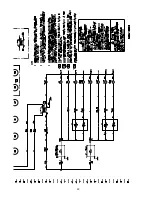
Typical Wiring Schematic .................................................. 28
See Figure 5-2: Figure 5-3
U
Unit Clearance ..................................................................... 6
See Figure 3-1
V
vacuum be “Broken” .......................................................... 21
Vacuum Pump Hookup ...................................................... 22
See Figure 4-1
vacuum pump oil ............................................................... 21
Vertical Lines ..................................................................... 16
W
Warnings .............................................................................. 4
Содержание CAUC-C80
Страница 5: ...5 General Information Continued Unit Component Layout and Shipwith Locations 120 Ton Unit Illustrated ...
Страница 8: ...8 Figure 3 2 CAUC C80 Unit Dimensional Data Recommended Clearances ...
Страница 9: ...9 Figure 3 2 Continued CAUC D10 Unit Dimensional Data Recommended Clearances ...
Страница 10: ...10 Figure 3 2 Continued CAUC D12 Unit Dimensional Data Recommended Clearances ...
Страница 19: ...19 Installation Continued Figure 3 5 Typical CAUC C80 through D12 Field Wiring Diagram ...
Страница 28: ...28 Figure 5 2 Typical Wiring Schematic for 80 through 120 Ton Units ...
Страница 29: ...29 ...
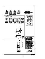
Страница 30: ...30 Figure 5 3 Typical Control Panel Connections Diagram for 80 through 120 Ton Units ...
Страница 31: ...31 ...
Страница 36: ...36 ...


