background image

12

Installation (Continued)

Spring Isolators

Install the spring isolators at each unit mounting (load)
point, using the following procedure:

1. Elevate the unit (one side at a time) to allow access to

the base rail mounting holes.

Note: Use solid type blocks, i.e. 4" X 4" wood
blocks or similar material to prevent collapsing.
Keep hands and other body limbs clear of elevated
base rail while installing isolators to prevent
personal injury.

2. Align the mounting holes in the base rail of the unit with

the positioning pin in the top of the appropriate isolator.
Refer to Figure 3-4 for the appropriate isolator for each
load point.

3. Position the isolator to allow access to the mounting

holes in the base of the isolator.

4. Lower the unit onto the isolator. The positioning pin on

the isolator must engage into the hole of the base rail.
The clearance between the upper and lower isolator
housings should be approximately 1/4 to 1/2 inch. Refer
to Figure 3-4. A clearance greater than 1/2 inch indicates
that shims are required to level the unit. Refer to the
“Leveling the Unit” section.

5. Make minor clearance adjustments by turning the isola-

tor leveling bolt (Figure 3-4) clockwise to increase the
clearance and counterclockwise to decrease the clear-
ance. If proper isolator clearance cannot be obtained by
turning the leveling bolt, level the isolators themselves.
A 1/4 inch variance in elevation is acceptable.

Rigging

A Rigging illustration and Center-of-Gravity dimensional
data table is shown in Figure 3-3. Refer to the typical unit
operating weights table before proceeding.

1. Rig the condensing unit as shown in Figure 3-3. Attach

adequate strength lifting slings to all four lifting brackets
in the unit base rail. Do not use cables, chains, or slings
except as shown.

2. Install spreader bars, as shown in Figure 3-3, to protect

the unit and to facilitate a uniform lift. The minimum dis-
tance between the lifting hook and the top of the unit
should be 7 feet.

3. Test-lift the unit to ensure it is properly rigged and bal-

anced, make any necessary rigging adjustments.

4. Lift the unit and position it into place.

Unit Isolation

To minimize unit sound and vibration transmission, one of
the following installation methods should be used:

1. Install the unit directly on an isolated (detached) concrete

pad or on isolated concrete footings located at each unit
load point.

2. Install the optional spring isolators at each mounting lo-

cation. Refer to the following “Spring Isolator” section.
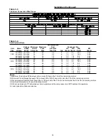
Figure 3-4

Typical Spring Isolator Selection & Location

Fin

Spring Isolator Part Number @ Mounting Location 

Unit Size Mat'l.

Location 1

2

3

4

5

6

7

8

C80

AL

CP-1D-900

CP-1D-900

CP-1D-900

CP-1D-900

CP-1D-900

CP-1D-900

CP-1D-900

CP-1D-900

CU

CP-1D-900

CP-1D-900

CP-1D-900

CP-1D-900

CP-1D-900

CP-1D-900

CP-1D-900

CP-1D-900

D10

AL

CP-1D-900

CP-1D-900

CP-1D-900

CP-1D-900

CP-1D-900

CP-1D-900

CP-1D-900

CP-1D-900

CU

CP-1D-1200

CP-1D-1200

CP-1D-1200

CP-1D-1200

CP-1D-1200

CP-1D-1200

CP-1D-1200

CP-1D-1200

D12

AL

CP-1D-1200

CP-1D-900

CP-1D-900

CP-1D-900

CP-1D-900

CP-1D-900

CP-1D-900

CP-1D-900

CU

CP-1D-1360

CP-1D-1200

CP-1D-1360

CP-1D-1200

CP-1D-1360

CP-1D-1200

CP-1D-1360

CP-1D-1200

Note:

1. Mounting locations correlate with those shown in point loading illustration.
2. The spring is marked with the full spring ID part # (ie CP-1D-900)
    If the isolator is color coded, there is a painted mark on each spring as follows;
    CP-1D-1200 = gray

CP-1D-1360 = white

    CP-1D-900 = dark green
3. Refer to the "Spring Isolator" section, step 4, for proper clearance.

Содержание CAUC-C80

Страница 1: ...8 e c n e u q e S Date October 2008 File No SV UN S S CAUC IOM 8 10 08 December 2001 s e d e s r e p u S TM Remote Air Cooled Condensers 2008Trane All rights reserved http www trane com Models J and Later Design Sequence CAUC C80 CAUC D10 CAUC D12 Note The installation of this equipment must comply with all National State and Local Codes Since the manufacturer has a policy of continuous product im...

Страница 2: ...wing the information within this manual and follow ing the instructions the risk of improper operation and or component damage will be minimized It is important that periodic maintenance be performed to help assure trouble free operation A maintenance schedule is provided at the end of this manual Should equipment failure occur contact a qualified service organization with qualified experienced HV...

Страница 3: ...4 Field Installed Control Wiring 14 Refrigerant Piping 15 Liquid Lines 15 Liquid Line Components 15 Discharge Hot Gas Lines 15 Discharge Line Components 16 Making Refrigerant Connections 16 Brazing Procedures 16 Leak Testing Procedure 17 Field Installed Power Wiring 17 Main Unit Power Wiring 17 Field Installed Control Wiring 20 Section Four System Pre Start Procedures System Evacuation Procedures ...

Страница 4: ...nd a third nameplate is located on the inside of the control panel door When ordering replacement parts or requesting service be sure to refer to the specific model number serial number and DL number if applicable stamped on the unit name plate Hazard Identification Warnings are provided through out this manual to indicate to installing contractors opera tors and service personnel of potentially h...

Страница 5: ...5 General Information Continued Unit Component Layout and Shipwith Locations 120 Ton Unit Illustrated ...

Страница 6: ...ppropriate Trane office before installing or re pairing a damaged unit Unit Clearances Figure 3 1 illustrates the minimum operating and service clearances for either a single multiple or pit application These clearances are the minimum distances necessary to assure adequate serviceability cataloged unit capacity and peak operating efficiency Providing less than the recommended clearances may re su...

Страница 7: ...7 Installation Continued Figure 3 1 Typical Installation Clearances for Single Multiple and Pit Applications ...

Страница 8: ...8 Figure 3 2 CAUC C80 Unit Dimensional Data Recommended Clearances ...

Страница 9: ...9 Figure 3 2 Continued CAUC D10 Unit Dimensional Data Recommended Clearances ...

Страница 10: ...10 Figure 3 2 Continued CAUC D12 Unit Dimensional Data Recommended Clearances ...

Страница 11: ...ing and Center of Gravity Data Location of Center of Shipping Gravity Unit Weight X Z Size Max Lbs In mm In mm C80 4542 81 2065 41 1052 D10 5371 106 2690 42 1062 D12 5971 106 2700 42 1064 LIFTING AND MOVING INSTRUCTIONS DO NOT USE CABLES CHAINS OR SLINGS EXCEPT AS SHOWN OTHER LIFTING ARRANGEMENTS MAY CAUSE EQUIPMENT DAMAGE OR SERIOUS PERSONAL INJURY EACH OF THE CABLES CHAINS OR SLINGS USED TO LIFT...

Страница 12: ...ng slings to all four lifting brackets in the unit base rail Do not use cables chains or slings except as shown 2 Install spreader bars as shown in Figure 3 3 to protect the unit and to facilitate a uniform lift The minimum dis tance between the lifting hook and the top of the unit should be 7 feet 3 Test lift the unit to ensure it is properly rigged and bal anced make any necessary rigging adjust...

Страница 13: ...el the unit carefully Use the unit base rail as a reference Level the unit to within 1 4 inch over its entire length Use shims if adjustable isola tors neoprene are not used If adjustable isolators spring are used ensure that the proper isolator housing clearance is maintained while level ing the unit Isolators are identified by color and or an isola tor part number Shims under the isolators may b...

Страница 14: ...ressor unit Refer to the Refrigerant Piping section for recommended discharge line components and guide lines Install shutoff valves in the liquid line s to isolate the fil ter drier s for service Install proper filter driers in each liquid line Leak test the system Refer to the Refrigerant Piping section for recommended procedures Main Electrical Power Requirements Verify the power supply meets t...

Страница 15: ...he unit sheet metal for the refrigerant piping entrance into the unit Liquid Line Components Filter driers and valves expansion valves charging valves etc should be provided in the liquid lines just before the evaporator Minimize the use of valves reducers and tube bends as much as possible to avoid excessive pressure drop before the expansion valve Liquid Line Filter Drier Install the filter drie...

Страница 16: ... enter the system which will contaminate the re frigerant system 6 Apply heat evenly over the length and circumference of the joint to draw the brazing material into the joint by capillary action Remove the brazing rod and flame from the joint as soon as a complete fillet is formed to avoid possible restriction in the line 7 Visually inspect the connection after brazing to locate any pin holes or ...

Страница 17: ...nd re make as a new joint Retest for leaks after making re pairs 8 Open the liquid line service valve and the compressor discharge service valve Field Installed Power Wiring An overall dimensional layout for the field installed wiring entrance into the unit is illustrated in Figure 3 2 To insure that the unit s supply power wiring is properly sized and in stalled follow the guidelines outlined bel...

Страница 18: ...8 22 25 25 12 1 0 1 8 9 0 0 90 575 60 3 520 635 17 15 20 12 1 0 1 4 7 2 0 90 200 60 3 180 220 50 50 60 12 1 0 4 1 20 7 0 90 D12 230 60 3 208 254 44 50 45 12 1 0 4 1 18 0 0 90 460 60 3 416 508 22 25 25 12 1 0 1 8 9 0 0 90 575 60 3 520 635 17 15 20 12 1 0 1 4 7 2 0 90 Notes 1 Maximum fuse size is 300 percent of one motor FLA plus the FLA of the remaining motors 2 Minimum Circuit Ampacity equals 125 ...

Страница 19: ...19 Installation Continued Figure 3 5 Typical CAUC C80 through D12 Field Wiring Diagram ...

Страница 20: ...e as listed in NEC 240 6 select the next higher standard fuse rating Note If the selected RDE is greater than the selected MOP value then select the RDE value to equal the MOP value Calculation 2 Disconnect Switch Sizing DSS DSS 1 15 X LOAD 1 LOAD 2 LOAD 4 Field Installed Control Wiring Before installing any connecting wiring refer to Figure 3 2 for the electrical access locations provided on the ...

Страница 21: ...tely 15 minutes This is referred to as a standing vacuum test where time versus pressure rise The maximum allowable rise over a 15 minute period is 200 microns If the pressure rise is greater than 200 microns but levels off to a constant value excessive moisture is present If the pressure steadily continues to rise a leak is indicated Figure 4 2 illustrates three possible results of the standing v...

Страница 22: ...Evacuation Time vs Pressure Rise 200 400 600 800 1000 1200 1400 1600 10 0 10 20 30 40 50 60 70 80 90 TIME IN MINUTES PRESSURE IN MICRONS Continuously increasing pressure indicates the presence of leaks moisture or both State of equilibrium indicates the true amount of moisture left in the system It indicates that no leaks are present but further evacuation is required State of equilibrium indicate...

Страница 23: ...trical Phasing Proper electrical phasing can be quickly determined and corrected before starting the unit by using an instrument such as an Associated Research Model 45 Phase Se quence Indicator and following the steps below Turn the field supplied disconnect switch that provides power to terminal block 1TB1 to the Off position H A Z A R D O U S V O LTA G E DISCONNECT ALL ELECTRIC POWER INCLUDING ...

Страница 24: ... 6K1 4B2 4B5 4B6 1 Circuit 1 Closed Open Customer Interlock 6K2 6K2 5B2 5B5 5B6 1 Circuit 2 Closed Open Fan Stage 1 Temperature 53 o F 45 o F 4B3 1 Switch Stage 2 1S42 2 73 o F 65 o F 4B1 4B4 1 Fan Stage 1 Temperature 53 o F 45 o F 5B3 1 Switch Stage 2 1S43 2 73 o F 65 o F 5B1 5B4 Notes 1 Bold fan identifies fans used on CAUC D10 D12 units only 2 1S42 and 1S43 normally closed contacts open on ambi...

Страница 25: ... 5 Check the condenser fans for proper rotation The direc tion of rotation is clockwise when viewed from the top of the unit All Fans are Rotating Backwards 1 Turn the field supplied disconnect switch or circuit protec tor switch that provides power to the condensing unit to the Off position Lock the disconnect switch in the open position while working at the unit 2 Interchange any two of the fiel...

Страница 26: ...e an accurate scale or a charging cylinder to monitor the amount of refrigerant entering the system Refer to Table 5 3 for the recommended refrigerant capacities for the condensing unit The weight of refrigerant required for the liquid line and liquid line driers are listed in Table 5 4 If the pressure within the system equalizes with the pres sure in the charging cylinder before charging is com p...

Страница 27: ...er foot Table 5 5 Sample Operator s Maintenance Log Refrigerant Circuit 1 Refrigerant Circuit 2 Current Ambient Compr Suct Disch Liquid Super Sub Compr Suct Disch Liquid Super Sub Temp Oil Press Press Press heat cool Oil Press Press Press heat cool Date F Level Psig Psig Psig F F Level Psig Psig Psig F F ok ok low low ok ok low low ok ok low low ok ok low low ok ok low low ok ok low low ok ok low ...

Страница 28: ...28 Figure 5 2 Typical Wiring Schematic for 80 through 120 Ton Units ...

Страница 29: ...29 ...

Страница 30: ...30 Figure 5 3 Typical Control Panel Connections Diagram for 80 through 120 Ton Units ...

Страница 31: ...31 ...

Страница 32: ...er lubrication can be just as harmful as not enough grease Use a hand grease gun to lubricate these bearings add grease until a light bead appears all around the seal Do not over lubricate After greasing the bearings check the setscrews to en sure that the shaft is held securely to the bearings and Fan wheels Make sure that all bearing supports are tight Check the supply fan belt s If the belts ar...

Страница 33: ...detergent selected is strongly alkaline ph value exceeds 8 5 add an inhibitor 1 Remove enough panels from the unit to gain access to the coil 2 Protect all electrical devices such as motors and control lers from any over spray 3 Straighten any bent coil fins with a fin comb 4 Mix the detergent with water according to the manufacturer s instructions If desired heat the solution to 150o F maximum to...

Страница 34: ...ssure regulating valve 16 pulling a vacuum of 100 microns 21 A Air Handling Equipment 32 Align the mounting holes 12 C CAUC C80 Unit Dimensional 8 See Figure 3 2 CAUC D10 Unit Dimensional Data 9 See Figure 3 2 CAUC D12 Unit Dimensional Data 10 See Figure 3 2 Cautions 4 clearance adjustments 12 COILOX 33 See Coil Cleaning compressor discharge service valve 21 concealed damage 6 concrete footings 12...

Страница 35: ...wn to be defective THE WARRANTY AND LIABILITY SET FORTH HEREIN ARE IN LIEU OF ALL OTHER WARRANTIES AND LIABILITIES WHETHER IN CONTRACT OR IN NEGLI GENCE EXPRESS OR IMPLIED IN LAW OR IN FACT INCLUDING IMPLIED WAR RANTIES OF MERCHANTABILITY AND FITNESS FOR PARTICULAR USE IN NO EVENT SHALL WARRANTOR BE LIABLE FOR ANY INCIDENTAL OR CONSEQUEN TIAL DAMAGES Manager Product Service American Standard Inc C...

Страница 36: ...36 ...

Отзывы: