


25
System Start-Up (Continued)
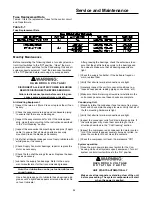
Figure 5-1
Condenser Fan Locations
Verifying Proper Condenser Fan Rotation
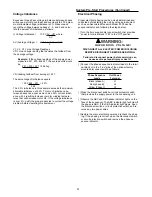
1. “Open” the field supplied disconnect switch or circuit pro-
tector switch that provides power to the compressor unit
and lock it in the “Off” position.
2. Open the disconnect switch or circuit protector switch
that provides power to the condensing unit.
3. Install temporary jumpers across terminals 1TB4-7 to
1TB4-9, 1TB4-7 to 1TB4-11, and the applicable cycling
controls, i.e., pressure switches and ambient thermo-
stats, to start the condenser fans, as illustrated in Figure
5-2.
R O T A T I N G P A R T S !
UNIT STARTS AUTOMATICALLY
Make sure all personnel are standing clear of the unit
before proceeding. The programmed components
will start when the TEST START time designated in
the previous step has elapsed.
4. “Close” the disconnect switch or circuit protector switch
that provides power to the condensing unit. Turn the con-
trol circuit switch 1S5 to the “On” position. The fans will
start when the power is applied.
5. Check the condenser fans for proper rotation. The direc-
tion of rotation is clockwise when viewed from the top of
the unit.
All Fans are Rotating Backwards;
1. Turn the field supplied disconnect switch or circuit protec-
tor switch that provides power to the condensing unit to
the “Off” position. Lock the disconnect switch in the open
position while working at the unit.
2. Interchange any two of the field connected main power
wires at the unit terminal block 1TB1 in the unit control
panel.
3. Remove all temporary jumpers previously installed in
step 3 of “Verifying Proper Condenser Fan Rotation”.
Note: Interchanging “Load” side power wires at the
fan contactors will only affect the individual fan
rotation. Ensure that the voltage phase sequence at
the main terminal block 1TB1 is ABC as outlined in
the “Electrical Phasing” section.
Some Fans are Rotating Backwards;
1. “Open” the field supplied disconnect switch upstream of
the unit. Lock the disconnect switch in the “Open” posi-
tion while working at the unit.
2. Interchange any two of the fan motor leads at the fan
contactor for each fan that is rotating backwards.
3. Remove all temporary jumpers previously installed in
step 3 of “Verifying Proper Condenser Fan Rotation”.
Содержание CAUC-C80
Страница 5: ...5 General Information Continued Unit Component Layout and Shipwith Locations 120 Ton Unit Illustrated ...
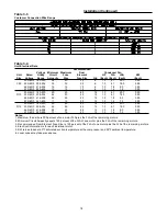
Страница 8: ...8 Figure 3 2 CAUC C80 Unit Dimensional Data Recommended Clearances ...
Страница 9: ...9 Figure 3 2 Continued CAUC D10 Unit Dimensional Data Recommended Clearances ...
Страница 10: ...10 Figure 3 2 Continued CAUC D12 Unit Dimensional Data Recommended Clearances ...
Страница 19: ...19 Installation Continued Figure 3 5 Typical CAUC C80 through D12 Field Wiring Diagram ...
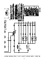
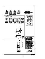
Страница 28: ...28 Figure 5 2 Typical Wiring Schematic for 80 through 120 Ton Units ...
Страница 29: ...29 ...
Страница 30: ...30 Figure 5 3 Typical Control Panel Connections Diagram for 80 through 120 Ton Units ...
Страница 31: ...31 ...
Страница 36: ...36 ...


