background image

BAS-SVX36C-EN

11

Installation

This section provides installation instructions.

Before you begin, read through the pre-installation information, beginning on

p. 9

, and also verify

the following conditions are met:

A wire access hole is available at the thermostat location.

The wires are accessible through the hole.

The wires are attached to the appropriate terminals on the HVAC equipment.

There is continuity (and not more than 2.5 ohms resistance) between the thermostat location

and the HVAC equipment.

The wires are accurately labeled or identified by color.

Mounting the Back Plate

WARNING

Hazardous voltage!

Disconnect all electric power, including remote disconnects before servicing. Follow proper
lockout/tagout procedures to ensure the power cannot be inadvertently energized. Failure to
disconnect power before servicing could result in death or serious injury.

NOTICE

Equipment damage!

Applying excessive voltage to the thermostat will permanently damage it.

To mount the back plate:

1.

Shut off power to the HVAC equipment.

Note:

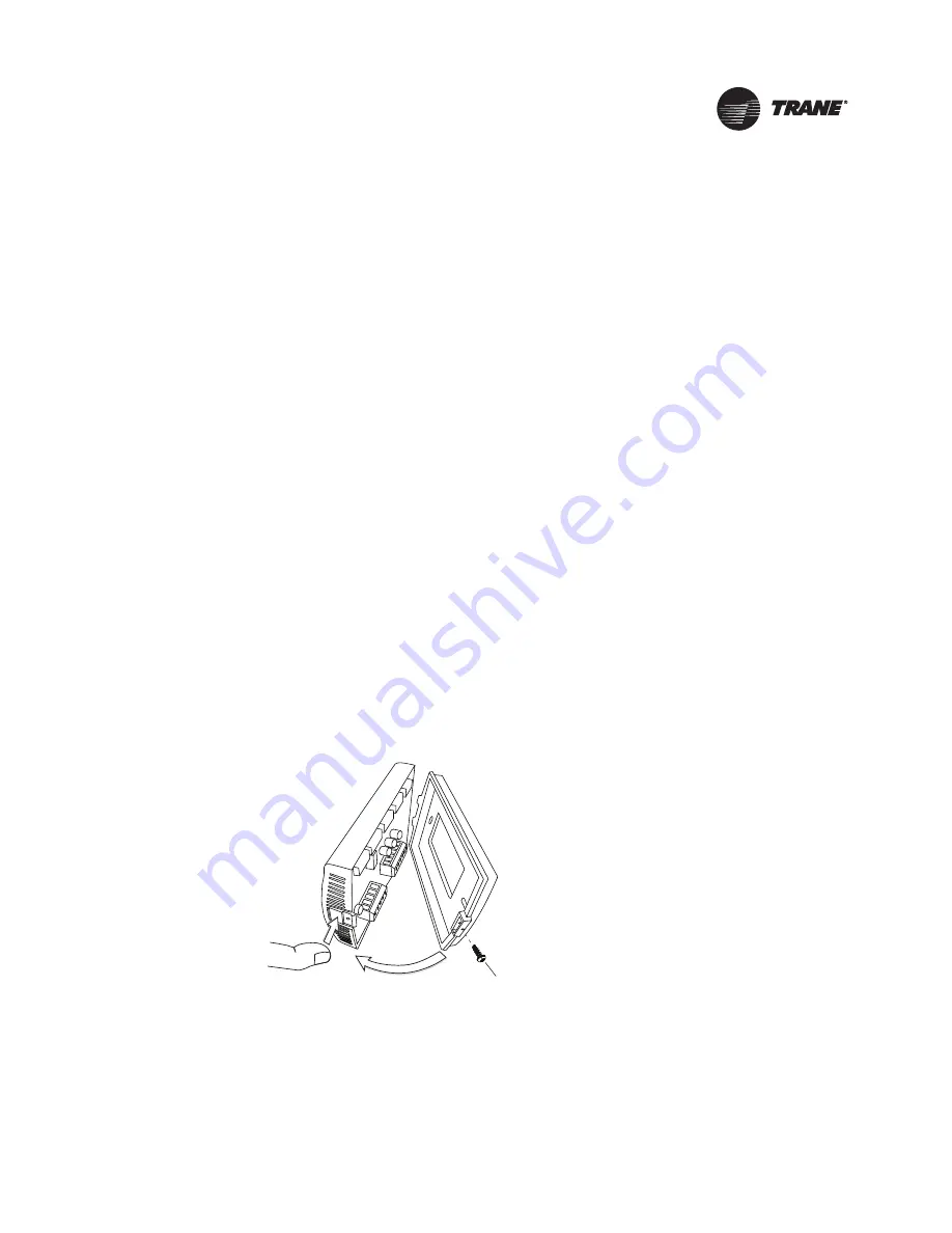
If the security screw is installed, remove it before attempting to remove the cover.
See

Figure 3

.

Figure 3.

Security screw

Security Screw Location (if used)

2. Remove the cover by firmly pressing the thumb tab at the bottom of the cover and pulling the

cover away from the back plate.

3. Feed the wires through the opening in the back plate.

Содержание 1H/1C

Страница 1: ...tarting up and servicing of heating ventilating and air conditioning equipment can be hazardous and requires specific knowledge and training Improperly installed adjusted or altered equipment by an unqualified person could result in death or serious injury When working on the equipment observe all precautions in the literature and on the tags stickers and labels that are attached to the equipment ...

Страница 2: ...ane in the United States and other countries All trademarks referenced in this document are the trademarks of their respective owners Warnings Cautions and Notices Warnings cautions and notices are provided in appropriate places throughout this document WARNING Indicates a potentially hazardous situation which if not avoided could result in death or serious injury CAUTION Indicates a potentially h...

Страница 3: ...mostat 14 3 Heat 2 Cool Non Programmable Thermostat 15 Programmable Thermostat 19 Replacing the Cover 24 Applying Power 25 Configuration 26 Operation 33 Icon Descriptions 33 Overview of Operation 33 Non Programmable Thermostats 34 Changing the System Mode 34 Showing or Changing the Heating or Cooling Temperature Setpoint 34 Changing the Fan Mode 35 Programmable Thermostats 35 Programming 35 Settin...

Страница 4: ...41 Configuration and Programming Retention 42 Extended Fan on Time Heat or Cool 42 Compressor and Auxiliary Heat Lockout 42 Auxiliary Heat Control 42 Economizer TOD 42 Troubleshooting 43 Error Codes 43 System Test Mode 43 Troubleshooting Table 47 Thermostat Specifications 48 ...

Страница 5: ...11536 01 Trane Clarksville part BAYSTAT155A Service parts THT02773 TheTrane non programmable 1 Heat 1 CoolThermostat Trane PLM X13511535 01 Trane Clarksville part BAYSTAT151A Service parts THT02772 Note To identify the thermostat type locate theTrane PLM and theTrane PLM Trane Clarksville on the thermostat circuit board The information contained in this document applies to either one or two models...

Страница 6: ... heat 2 heat 2 cool conventional 2 heat 1 cool conventional 1 heat 2 cool conventional 2 heat 2 cool heat pump without auxiliary heat 3 heat 2 cool heat pump with auxiliary heat A heating and cooling setpoint range of 40ºF to 90ºF 4 5ºC to 32ºC Two fan modes On Auto Additional configurable options See Configuration p 26 Terminals and configuration options for a remote temperature sensor Options in...

Страница 7: ...ammable thermostats have the same dimensions the programmable thermostat has slightly different dimensions Figure 1 ProgrammableThermostat Dimensions 3 25 in 83 mm 1 08 in 27 5 mm 4 7 in 119 mm 0 3 in 8 mm Typ P Radius 0 08 in 2 mm 3 4 in 86 mm Note Drawing not to scale Dimensions within 0 02 in 0 5 mm Typ Radius 0 08 in 2 mm ...

Страница 8: ...Heat 1 Cool or 3 Heat 2 Cool non programmable Thermostat Dimensions 3 07 in 78 mm 1 1 in 28 mm 4 7 in 119 mm 0 3 in 8 mm Typ P Radius 0 08 in 2 mm 3 4 in 86 mm Note Drawing not to scale Dimensions within 0 02 in 0 5 mm Typ Radius 0 08 in 2 mm ...

Страница 9: ...amage or tampering Height Requirements It is recommended that you mount the back plate a maximum distance of 54 in 137 cm above the floor If a parallel approach by a person in a wheelchair is required reduce the maximum height to 48 inches Note Consult section 4 27 3 of the 2002Americans with DisabilityAct guideline and local building codes for further details regarding wheelchair requirements Mou...

Страница 10: ...e slight errors in the measurement For the highest temperature reading accuracy avoid exceeding the maximum recommended wire lengths shown in Table 2 Note For 22 AWG 0 33 mm2 copper wires the rate of error can be up to 0 5 F 0 3 C per 100 which typically requires wire lengths in excess of 5000 ft 1500 m Table 1 MaximumThermostat to HVAC Equipment Wire Lengths Copper wire size Maximum recommended w...

Страница 11: ...WARNING Hazardous voltage Disconnect all electric power including remote disconnects before servicing Follow proper lockout tagout procedures to ensure the power cannot be inadvertently energized Failure to disconnect power before servicing could result in death or serious injury NOTICE Equipment damage Applying excessive voltage to the thermostat will permanently damage it To mount the back plate...

Страница 12: ...serious injury NOTICE Equipment damage Applying excessive voltage to the thermostat will permanently damage it General Practice To wire the thermostat 1 Connect the wires to the terminal block s packaged in the box with the thermostat The programmable thermostat has two terminal blocks the non programmable thermostats have only one Remove approximately 1 4 inch 6 mm of insulation from the wires Us...

Страница 13: ...nd the back plate 4 Use nonflammable insulation to prevent air movement between the wall cavity and the thermostat Terminal Identification The table below defines the terminals for each of the thermostat types Terminal Label Terminal Description Where present 1H 1C Thermostat p n X13511535 01 3H 2C Thermostat p n X13511536 01 Programmable Thermostat p n X13511537 01 C Common G Fan Relay Y Stage 1 ...

Страница 14: ...Fan L2 L1 hot 24 Vac Heat Compressor L2 L1 hot 24 Vac Cooling Transformer Heating Transformer Two Transformers jumper removed Figure 7 1H 1CThermostat 1H 1C Heat Pump Without Auxiliary Heat Option 1 jumper installed Rc R Y C O B G Fan L2 L1 hot 24 Vac Changeover Valve Compressor Table 3 SystemType Options for 1H 1C Non ProgrammableThermostats System Type Value for Option 01 See Diagram 1 heat 1 co...

Страница 15: ...rams that follow to correctly wire the thermostat for your system type Table 4 SystemType Options for 3H 2C Non ProgrammableThermostats System Type Value for Option 01 See Diagram 1 heat 1 cool conventional 0 Figure 11 1 heat 1 cool heat pump without auxiliary heat 1 Figure 12 1 heat only conventional without fan 2 Figure 13 1 heat only conventional with fan 3 Figure 14 1 cool conventional 4 Figur...

Страница 16: ...ac Heat Compressor L2 L1 hot 24 Vac Cooling Transformer Heating Transformer Two Transformers jumper removed Figure 12 3H 2C Non ProgrammableThermostat 1H 1C Heat Pump Without Auxiliary heat Option 1 Rc R Y Aux E Y2 L C O B G Fan L2 L1 hot 24 Vac Changeover Valve Compressor jumper installed Figure 13 3H 2C Non ProgrammableThermostat 1H Only Conventional Without Fan Option 2 Rc R Y W2 Y2 L C W G L2 ...

Страница 17: ...er installed Figure 15 3H 2C Non ProgrammableThermostat 1C Conventional Option 4 Rc R Y W2 Y2 L C W G Fan L2 L1 hot 24 Vac Compressor jumper installed Figure 16 3H 2C Non ProgrammableThermostat 2H 1C Heat Pump With Auxiliary Heat Option 5 Rc R Y Aux E Y2 L C O B G Fan L2 L1 hot 24 Vac Auxiliary Heat Changeover Valve Compressor jumper installed Zoning Panels ...

Страница 18: ...er removed Figure 18 3H 2C Non ProgrammableThermostat 1H 2C Conventional Option 7 Rc R Y W2 Y2 L C W G Fan L2 L1 hot 24 Vac Heat Compressor 1 Compressor 2 Single Transformer jumper installed Rc R Y W2 Y2 L C W G Fan L2 L1 hot 24 Vac Heat Compressor 1 Compressor 2 L2 L1 hot 24 Vac Cooling Transformer Heating Transformer Two Transformers jumper removed Figure 19 3H 2C Non ProgrammableThermostat 2H 2...

Страница 19: ...ptions for ProgrammableThermostats System Type Value for Option 130 See Diagram 1 heat 1 cool conventional 1 Figure 21 1 heat 1 cool heat pump without auxiliary heat 2 Figure 22 1 heat only conventional without fan 3 Figure 23 1 heat only conventional with fan 4 Figure 24 1 cool conventional 5 Figure 25 2 heat 1 cool heat pump with auxiliary heat 6 Figure 26 2 heat 2 cool conventional 7 Figure 27 ...

Страница 20: ...r installed Fan L2 L1 hot 24 Vac Heat Compressor L2 L1 hot 24 Vac Cooling Transformer Heating Transformer Two Transformers C G Y W Rc R W2 Y2 A S1 S2 jumper removed Economizer TOD Remote Temperature Sensor Figure 22 ProgrammableThermostat 1H 1C Heat Pump Without Auxiliary Heat Option 2 Fan 24 Vac C G Y O B Rc R W1 Y2 A S1 S2 Changeover Valve Compressor L2 L1 hot jumper installed Economizer TOD Rem...

Страница 21: ... TOD Remote Temperature Sensor Figure 24 ProgrammableThermostat 1H Conventional With Fan Option 4 Fan 24 Vac C G Y W Rc R W2 Y2 A S1 S2 Heat L2 L1 hot jumper installed Economizer TOD Remote Temperature Sensor Figure 25 ProgrammableThermostat 1C Conventional Option 5 Fan 24 Vac C G Y W Rc R W2 Y2 A S1 S2 Compressor L2 L1 hot jumper installed Economizer TOD Remote Temperature Sensor ...

Страница 22: ...e Sensor Figure 27 ProgrammableThermostat 2H 2C Conventional Option 7 Fan 24 Vac C G Y W Rc R W2 Y2 A S1 S2 Heat 1 Compressor 1 Heat 2 Compressor 2 L2 L1 hot Single Transformer jumper installed Economizer TOD Remote Temperature Sensor Fan L2 L1 hot 24 Vac Heat 1 Heat 2 Compressor 1 Compressor 2 L2 L1 hot 24 Vac Cooling Transformer Heating Transformer Two Transformers C G Y W Rc R W2 Y2 A S1 S2 jum...

Страница 23: ...ansformer Two Transformers C G Y W Rc R W2 Y2 A S1 S2 jumper removed Economizer TOD Remote Temperature Sensor Figure 29 ProgrammableThermostat 1H 2C Conventional Option 9 Fan 24 Vac C G Y W Rc R W2 Y2 A S1 S2 Heat Compressor 1 Compressor 2 L2 L1 hot Single Transformer jumper installed Economizer TOD Remote Temperature Sensor Fan L2 L1 hot 24 Vac Heat Compressor 1 Compressor 2 L2 L1 hot 24 Vac Cool...

Страница 24: ...at Pump With Auxiliary Heat Option 11 Fan 24 Vac C G Y O B Rc R W1 Y2 A S1 S2 Changeover Valve Compressor 1 Compressor 2 L2 L1 hot jumper installed Auxiliary Heat Economizer TOD Remote Temperature Sensor Replacing the Cover To replace the cover 1 Hook the cover over the top of the back plate Apply light pressure to the bottom of the cover until it snaps in place 2 If desired install the security s...

Страница 25: ... firmware version shows in the HH MM digits On the non programmable thermostats the digits are split between the top and bottom regions of the screen the most significant digits are at the top 3 Power up tests are performed If an error is detected an error code appears see Error Codes p 43 If no errors are detected the home screen appears see Figure 33 Figure 33 Home screens Mo AM Programmable the...

Страница 26: ...WARNING Live Electrical Components The circuit board is energized Have a qualified licensed electrician or other individual who has been properly trained in handling live electrical components perform this step Failure to follow all electrical safety precautions when exposed to live electrical components could result in death or serious injury a Remove the thermostat cover b Press and hold the con...

Страница 27: ...2 12 hour clock 24 24 hour clock 0120 Year 09 09 99 2009 2099 0121 Month 1 1 12 Months of the year 0122 Day 1 1 31 Days of the month 0125 Daylight savings 2 0 Disabled 1 US 1987 changeover at 2 00am 2 US 2007 changeover at 2 00am 3 Europe changeover at 1 00am 4 Manual changeover at 2 00am 0126 Spring month 1 03 01 12 The month in which the Spring daylight savings change occurs 0127 Spring day 08 0...

Страница 28: ...for emergency heat 2 9 1 10 Cycles per hour for emergency heat only for heat pump systems with more heat than cool stages 0170 Continuous backlight 0 0 Backlight ON time is limited 1 Backlight does not turn off 0180 Changeover 1 0 Manual changeover heat cool off manually changeover the thermostat between heat cool and off 1 Auto changeover heat cool auto off manually changeover between heat cool a...

Страница 29: ...ed 9 Unoccupied Occupied 10 Unoccupied Unoccupied 11 Unoccupied Occupied 12 Occupied Unoccupied 13 Occupied Occupied 14 Occupied Unoccupied 15 Occupied Occupied If Option 0231 is set to 4 Morning Day Evening Night 0 Unoccupied Unoccupied Unoccupied Unoccupied 1 Unoccupied Unoccupied Unoccupied Occupied 2 Unoccupied Unoccupied Occupied Unoccupied 3 Unoccupied Unoccupied Occupied Occupied 4 Unoccupi...

Страница 30: ... options to default except calendar and system selection options 0120 0122 and 0125 0130 do not reset 1 Only available if option 0125 is set to 4 2 See Heat and Cool Cycling Rate p 41 3 See Deadband p 41 4 If an external sensor is attached to the S1 and S2 terminals it must be 10K negative temperature coefficient 5 Only available for heat pump systems with more heat than cool stages and remote out...

Страница 31: ... cool and off or select automatic changeover 2 Auto changeover only auto no manual changeover 07 Temperature indication resolution 0 0 F with 1 degree resolution 1 F with 0 5 degree resolution 2 C with 1 degree resolution 3 C with 0 5 degree resolution 4 C with 0 1 degree resolution 08 Compressor protection 5 0 5 Minutes for compressor off time only available on heat pump systems or systems with c...

Страница 32: ...uto changeover 0 0 Manual changeover heat cool off manually changeover between heat cool and off 1 Auto changeover heat cool auto off manually changeover between heat cool and off or select automatic changeover 2 Auto changeover only auto no manual changeover 07 Temperature indication resolution 0 0 0 F with 1 degree resolution 1 F with 0 5 degree resolution 2 C with 1 degree resolution 3 C with 0...

Страница 33: ...tically AM PM DAYS HOURS Mo Tu We Th Fr Sat Su Large numeric display Shows current temperature but can indicate other information Temperature units F or C Setpoint indicator upper arrow indicates cooling setpoint lower arrow indicates heating setpoint Heating mode indicator heating cooling automatic heating cooling or off Period indicator morning day evening night Time of day 12 hour clock with AM...

Страница 34: ...g upon the model and system type the thermostat can be set to one of five modes Cooling Heating Emergency Heat Auto or Off Note The 1 Heat 1 Cool thermostat does not have Emergency Heat mode To change the system mode 1 Press The current mode flashes 2 Press or to select a mode 3 Tap or wait 5 sec to save and exit Showing or Changing the Heating or CoolingTemperature Setpoint To change the heating ...

Страница 35: ... time of day for scheduling purposes Programming This section describes how to program the thermostat after it has been installed and configured Setting theTime The time must be set in the thermostat to ensure operation of the schedule Note The date is set during configuration and the day of the week is calculated automatically according to the date To set the time 1 Press The hour flashes to indi...

Страница 36: ...day all follow the same schedule Saturday and Sunday each follow their own schedules 5 2 days Monday Friday all follow the same schedule Saturday and Sunday follow the same schedule which is different than the Monday Friday schedule 7 days Each day follows its own schedule Note See Configuration p 26 to change the number of periods in a day or the grouping of days in the schedule If needed you can...

Страница 37: ...ult settings Day 6 00 am 70 F 21 0 C 78 F 25 5 C Auto Night 10 00 pm 55 F 13 0 C 85 F 29 5 C Auto Monday Morning Auto On Day Auto On Evening Auto On Night Auto On Tuesday Morning Auto On Day Auto On Evening Auto On Night Auto On Wednesday Morning Auto On Day Auto On Evening Auto On Night Auto On Thursday Morning Auto On Day Auto On Evening Auto On Night Auto On Friday Morning Auto On Day Auto On E...

Страница 38: ...selection If there is a heat mode configured the heat setpoint appears and its icons start flashing 9 Press or to select the heating setpoint Note The heating and cooling setpoints cannot be closer together than the deadband which is specified in installer configuration option 0181 see Configuration p 26 If you raise the heating setpoint or reduce the cooling setpoint to a value that would violate...

Страница 39: ...rammable thermostat to be configured to be a non programmable thermostat If installation configuration option 140 is set to 0 schedule programming capabilities will be absent Showing the Setpoint orTemperature on Display Depending upon the value of configuration option 210 the large numeric display could show any of the following Figure 37 Display Options To switch between the current temperature ...

Страница 40: ...you reach the function you want to change as part of the override press and make the changes 5 Once you have specified all needed changes press and hold for 2 sec or wait 15 sec to save and exit 6 Press and hold and for 2 sec from the home screen or when inTOV setup mode to exit without enteringTOV mode Locking or Unlocking Modes You can independently lock and unlock the system fan and schedule ch...

Страница 41: ...h variable duty cycle Depending on the heating or cooling load which is measured by feedback from the sensor thermistor and or temperature error the system could run at 50 duty cycle 6 min ON and 6 min OFF 80 duty cycle 9 6 min ON and 2 4 min OFF or other variations of the duty cycle Note The cycling rate described above is only active when the temperature is within the temperature differential If...

Страница 42: ...ump systems with more heat stages than cool stages When the temperature from an outdoor sensor is above the auxiliary lockout point only the compressor will operate on a call for heat below the compressor lockout point only the auxiliary heat will operate on a call for heat between the compressor and auxiliary lockout point the compressor and auxiliary heat will operate on a call for heat There is...

Страница 43: ...tem test mode 1 Apply electrical power to the thermostat 2 Enter installer configuration mode Table 10 Error Codes Code Description E0 Thermistor Error occurs when the configured thermistor reading is out of range less than 14 F 9 9 C or greater than 122 F 50 C If this error occurs All Heat Cool outputs turn off If the fan mode is Auto the thermostat turns off the fan If the fan mode is On the the...

Страница 44: ...mall digits at the lower part of the display The test setting value appears in large digits at the top part of the display Figure 40 SystemTest Mode Note System test mode automatically ends if no buttons are pressed for 10 min While in system test mode you can scroll from one test to the next change the value for the test then test or observe the system for the expected result The numbers and valu...

Страница 45: ...value of the power up test test number 8 for the 1 Heat 1 Cool thermostat test number 11 for the 3 Heat 2 Cool or programmable thermostat to 1 to run a power up test after you exit test mode 8 Do one of the following to exit test mode Remove the thermostat cover if necessary and then press and immediately release the configuration button Do not press any buttons for 10 min Press and hold for 2 sec...

Страница 46: ...This setting remains active when you scroll to the next setting NA 6 NA Emergency Heat 0 Emergency relay fan and terminal L output turn off 1 Emergency relay fan and terminal L output turn on This setting remains active when you scroll to the next setting 5 8 6 LCD segments 0 full segment on 1 odd segments on even segments off 2 even segments on odd segments off This setting is deactivated when yo...

Страница 47: ...k have the thermostat serviced or replaced by a qualified Trane supplier Erratic display appearance or contrast Check the power supply Check the frequency configuration Configuration option 210 for the programmable thermostat or 11 for non programmable thermostats to make sure that you are using the correct frequency setting for your power supply If the power supply and frequency setting are ok ha...

Страница 48: ...option 190 24Vac 50Hz or 60Hz 18Vac to 32Vac Power supply frequency selected using installation configuration option 11 Wire size 18 to 22 AWG 18 to 22 AWG Output terminal ratings 1A 30Vac 1A 30Vac Indoor temperature display range 15 to 122 F 9 5 to 50 C 32 to 99 F 0 to 37 C Outdoor remote temperature display range 31 to 122 F 35 to 50 C NA Storage temperature 40 to 158 F 40 to 70 C 40 to 158 F 40...

Отзывы: