background image

15

Installation

withstanding high temperatures
without degradation.

C

CA

AU

UT

TIIO

ON

N

A defect in fixing or insulating the
condensation sensors may cause
incorrect adjustment and/or damage
to the compressor.

If the sensor cannot be mounted in
the place where the saturated gas
enters the sub-cooler, it must be
positioned on the sub-cooler side
and not on the condenser side. If the
condenser temperature cannot be
measured, it is preferable to
measure the liquid temperature
instead of the discharge
temperature.

C

CA

AU

UT

TIIO

ON

N

To prevent interference, separate the
sensor cables from the power cables.

Electrical connections
performed by the installer

All wiring must comply with local
codes. Specific electrical schematics
and connection diagrams are
shipped with the unit.

C

CA

AU

UT

TIIO

ON

N

To avoid corrosion and overheating
at terminal connections, use copper
conductors only. Failure to do so
may result in damage to the
equipment. Do not allow conduit to
interfere with other components,
structural members or equipment.
Control voltage (110 V) wiring in
conduit must be separate from
conduit carrying low voltage (<30 V)
wiring. To prevent control
malfunctions, do not run low voltage
wiring (<30 V) in conduit with
conductors carrying more than 30 V.

Connecting the RTUB with a remote
air-cooled condenser

The RTUB unit is shipped with a
holding nitrogen charge and a
separate oil charge. The RTCA
condenser is designed to operate
with the RTUB unit. To ensure
optimum operation and
performance, the RTUB must be
installed with the RTCA condenser. If

correctly, refer to the general
recommendations. Connect the
outside air sensor 5R3 to terminals 1
and 2 on terminal board 1. Connect
the condenser sensor 5R56-1 to
terminals 4 and 5 on terminal board
J4 on module A20-1. Connect the
condenser sensor 5R56-2 to
terminals 4 and 5 on terminal J4 on
module A20-2.

If the condenser is not an RTCA,
ambient temperature and condenser
temperature sensors must be
connected to the RTUB to monitor it.
The ambient temperature sensor
must be installed in a position which
represents most accurately the
condenser's surrounding
environment. It must not be exposed
to sunlight or precipitation. Ensure
that the sensor is not located in the
flow of recycled air from the
condenser discharge. The
condensation temperature sensors
must be installed on the refrigerant
piping at the place where it leaves
the condenser to enter the sub-
cooler. It is necessary to install a
condenser temperature sensor on
each refrigerant circuit. This sensor
must be fixed in compliance with the
method used to attach the bulb for a
thermostat expansion valve. This
sensor can be fixed outside the
piping if it is sufficiently insulated
with insulation capable of

convenient position. Plug the sensor
cable and the cable connected to the
control panel into the junction box.
The shielded cable can be cut to the
required length.
Note: To lengthen the sensor's power
cable, use 0.75 to 1.25 mm²
conductors, 600V. The cable used
between the junction box and the
control panel must either be shielded
or in a duct. If a shielded cable is
used, make sure it is not used with
other cables carrying 30 V or more.

Evaporator leaving water
temperature sensor 5R51 (standard)

Install this temperature sensor in the
evaporator's leaving water piping
system. To install it correctly, refer to
the general recommendations.
Connect this sensor to terminals
X7-1 and X7-2.

Evaporator entering water
temperature sensor 5R52 (standard)

Install this sensor in the evaporator
water piping. To install it correctly,
refer to the general
recommendations. Connect this
sensor across terminals X6-1 and
X6-2.

Condenser sensors 5R56-1, 5R56-2,
5R3 (option)

If an RTCA condenser is used with an
RTUB, the sensors required are
installed on the RTCA. To install them

1

6

7

3

4

5

2

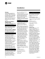
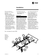
Figure 9: UCM water temperature sensor installation

1 In
2 Out
3 UCM sensor
4 ¼" NPT coupling (customer-supplied)

5 Compression fitting (Trane-supplied)
6 Fitting body
7 Clamping nut

RLC-SVX03A-E4

Содержание 108-216

Страница 1: ...Installation Operation Maintenance RTUB 207 224 Liquid chillers with helical rotary compressors RTCA 108 216 Remote air cooled condenser RLC SVX03A E4...

Страница 2: ...delivery note and send a registered letter of protest to the last carrier of the goods within 72 hours of delivery Notify the localTrane Sales Office at the same time The unit should be totally inspe...

Страница 3: ...a RTCA 8 Installation Installation Responsibilities 9 Storage 9 Special Lifting and Moving Instructions 10 Isolation 10 Foundation 10 Clearances 11 Drainage 12 Releasing the Nitrogen Holding Charge 12...

Страница 4: ...Temporary Shutdown and Restart 23 Extended Shutdown Procedure 23 System Restart after Extended Shutdown 23 Maintenance Periodic Maintenance 25 Refrigerant and Oil Charge Management 27 R134a Field char...

Страница 5: ...ane Sales Office Do not proceed with installation of a damaged unit without sales office approval Inspection Checklist To protect against loss due to damage incurred in transit complete the following...

Страница 6: ...l for shipment Description of the Unit The RTUB units are liquid chillers equipped with two helical rotary compressors and an evaporator designed to operate with remote RTCA air cooled condensers or o...

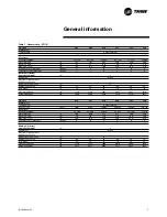
Страница 7: ...ng Weight kg 2130 2130 2845 2845 2845 3250 Shipping Weight kg 1860 1860 2570 2570 2570 2975 Unit size 216 217 218 220 222 224 Compressor Type Quantity Helical rotary 2 Nominal size tons 70 85 85 85 10...

Страница 8: ...8 1 5 8 1 5 8 Liquid connection inches 1 1 8 1 1 8 1 1 8 1 1 8 1 1 8 1 1 8 Unit size 208 209 211 213 215 216 Condenser Condenser type Aluminium fins copper tubes Fin spacing fins ft 168 168 144 168 16...

Страница 9: ...for RTUB Furnish and install strainers ahead of all pumps and automatic modulating valves Furnish and install check valves on the discharge lines between oil separators and condenser in order to avoi...

Страница 10: ...e sound transmitted through water piping To reduce the sound transmitted through electrical conduit use flexible electrical conduit State and local codes on sound emissions should always be considered...

Страница 11: ...igure 5 andTable 4 for unit Figure 5 Unit Dimensions and Recommended Minimum Clearances RTCA Figure 6 Unit Dimensions and Recommended Minimum Clearances RTUB A C D B A C D B Table 4 Unit Dimensions an...

Страница 12: ...n transmission through the water lines If desired install thermometers in the lines to monitor entering and leaving water temperatures Install a balancing valve in the leaving water line to control wa...

Страница 13: ...tween the water and system components Foreign matter in the chilled water system can also increase pressure drop and consequently reduce water flow Proper water treatment must be determined locally de...

Страница 14: ...es for relief valve installation guidelines Installing and connecting temperature sensors General Recommendations Regardless of the type of monitoring sensor required by a particular application the s...

Страница 15: ...ambient temperature and condenser temperature sensors must be connected to the RTUB to monitor it The ambient temperature sensor must be installed in a position which represents most accurately the c...

Страница 16: ...its each with its own ventilation The ventilation cannot be common to the two circuits For this type of installation non RTCA condenser an On Off signal is available on the unit control module UCM of...

Страница 17: ...commended to place a trap on the discharge line at the oil separator outlet if this discharge line is horizontal for a distance greater than 5 m at a height greater than the connection to the oil sepa...

Страница 18: ...n the two units must not exceed 60 m in reality or the equivalent of 90 m taking into account pressure drops The height of the liquid line in relation to the condenser base must be less than 5 m Legen...

Страница 19: ...uction line using the following criteria 1 2 5 m s minimum in the horizontal parts 2 5 0 m s minimum in the vertical parts 3 Maximum speed 20 m s The minimum slope of the suction line to the condenser...

Страница 20: ...ent manometer must be installed upstream of the vacuum pump stop valve 1 Close valve B and open valve A After a few minutes the manometer reading indicated the lowest vacuum level that can be obtained...

Страница 21: ...f untreated or improperly treated water or saline or brackish water Close the fused disconnect switch es that supplies power to the chilled water pump starter Start the chilled water pump to begin cir...

Страница 22: ...ions prior to start up have been performed see previous sections the unit is ready to start Press the Stop key on the UCM CLD If necessary adjust the setpoint values in the UCM CLD reports refer to th...

Страница 23: ...ain glycol to prevent any risk of evaporator freeze up Extended period shutdown The procedure below must be performed if the system has to be stopped for a prolonged period for example seasonal shutdo...

Страница 24: ...Flow Rates and Water System Pressure Drop 7 Adjust the flow switch on the evaporator piping for proper operation 8 Stop the water pump The unit is now ready for startup as described in Startup Proced...

Страница 25: ...even more if conditions are very poor or if corrosion damage begins to occur To clean the coils use a soft brush and a sprayer garden pump up type A high quality detergent such as Trane Coil Cleaner...

Страница 26: ...ser 2 After the compressor stops close the compressor discharge valve and disconnect the unit Note Do not make successive vacuums by using the compressor Irreversible compressor damage could occur 3 V...

Страница 27: ...line due to high vapor velocity High Condenser Subcooler Pressure drop Some symptoms of a refrigerant over charged unit High subcooling Larger than normal condenser approach temperatures Entering Con...

Страница 28: ...tenance on the compressor or high side It is much more preferable to isolate the charge in the evaporator if this option is available High side charge isolation procedure 1 Make sure the circuit is of...

Страница 29: ...he oil system is critical to the reliability of the compressor and chiller Too little oil can cause the compressor to run hot and inefficiently When taken to an extreme low oil level may result in inf...

Страница 30: ...s than 15 minutes If the oil charge is removed from the compressor and oil system only and the unit has been run for more than 15 minutes However reduce the amount of oil added to the unit by the norm...

Страница 31: ...tainer or is otherwise contaminated then this small volume must be subject to vacuum as well However the filter cavity is full of oil Therefore be sure to use a flash tank in line with the vacuum pump...

Страница 32: ...stem should be carried out only by qualified and experienced personnel Maintenance contract It is strongly recommended that you sign a maintenance contract with your local Service Agency This contract...

Отзывы: