TU600-X
Trackunit TU600-X, Technical Manual v1.0, December 2019
Page 14
Connections
The connections depend on the type of vehicles / machines etc. in which the (GSM/LTE M1/NB
IOT)/GPS unit is to be installed.
Different variants of the TU600-X device will have only a subset of the connections shown in the
table below. Please contact your nearest sales office, distributor or “Reseller” for further
information about the availability of other variants in your area.
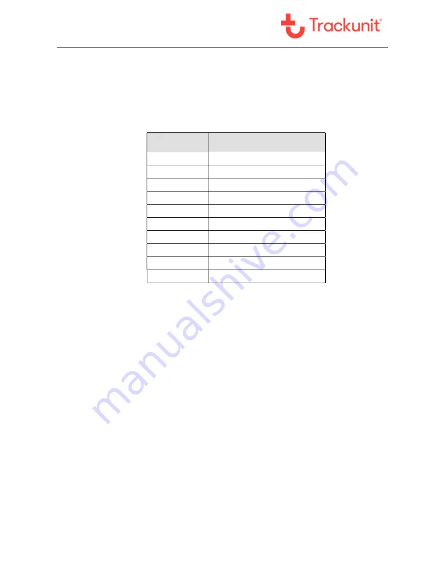
Wire
(color code)
TU600-X function
Red
Supply v12V / +24V
White
Digital input 1
Brown
Digital input 2 (Ignition)
Grey
Digital input 3
Yellow
Digital output 1
Green
1-Wire input (M8 Connector)
Pink
Digital input 4
Orange
CAN HI (Optional)
Light Blue
CAN LO (Optional)
Blue
Common ground
Power supply
The unit
must
be connected to 12V, +24V battery voltage through a 1A/32V fuse or +36V,
+48V battery through 3A/80V fuse. The use of a fused supply wire is important for not damaging
the wires related to the unit in case of a short circuit etc.
Digital inputs
The activation of a digital input requires a minimum high-level voltage of 9,5V.
Digital output
The digital output has the type indication” LO-side switch”, that connects the output to 0V “ground”,
when the output is active. This output can be used to control a relay powered from an external DC
supply voltage. The maximum current drawn from the output is 200mA.
The output is protected against short circuits, overload and is also protected against over voltage.
For further information about connection possibilities of the digital output, see chapters about
installation later in this manual.
Motion/acceleration sensor
The unit has a built-in 3 axis acceleration sensor that can activate the unit if it, as a consequence
of disconnected supply voltage, is in stand-by mode (theft protection), log accelerometer data (for
analyzing shock and machine behavior) or configured as a tilt-sensor.
CAN interface
TU600 is equipped with a built-in CAN Controller.
Protocols supported: SAE J1939 and CANopen. The CAN interface is Fully Compliant with CAN
2.0 Part A and 2.0 Part B. 8 independent message objects (mailboxes) are implemented, and


