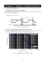
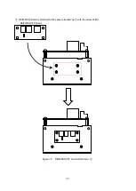


43
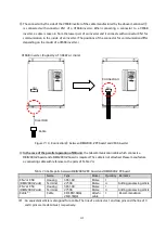
7.1.5 Station number set-up
At the time of communication option substrate use, a setup of a station number is required of F20 set-up
mode (Power supply voltage selection and Master/Slave selection and Station number set-up mode)
.
Refer
to the "5.4.3 F20 (Power supply voltage selection and Master/Slave selection and Station number set-up
mode) for the procedure of a setup.
If the abnormalities in communication or DB unit becomes protection mode, it will be displayed as "dbO"
on a VF66B series inverter. "O" is the code set up in F20 setting mode. Refer to "9.4 Protection oat the time
of communication option use" for protection mode.
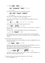
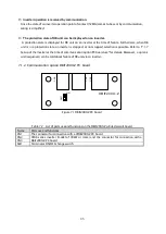
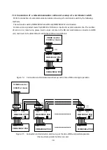
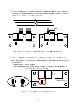
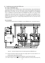
7.1.6
Main circuit wiring at the time of communication option PC board attachment
In the time of communication option substrate attachment, the time usually differs from wiring. About
Master/Slave selestion and power supply voltage selection, it is usually the same as that of the time. "5.2.1
Change of power supply voltage" and "5.2.2 Set-up of single operation or Master/Slave system operation"
are referred to,Please perform various setup.
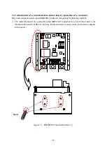
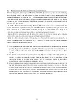
◎
Single operation
1
2
3
4
5
6
8
9
7
P
PR
N
OCRY
DBR
CN2
CN3
400V
200V
TH
8 8 8
SHT
OCRY
52MAX
M
TB2
DB_IN
DB_ON
86A
52MA
MCCB
MC
R
S
T
1
2
U
V
W
DCL
※
CN1
1
4
1
4
DBIF2009-Z
CN2 or CN3
RUNNING SIGNAL
VF66B INVERTER
UNIT
(30kW or more)
In
v
er
ter
O
p
er
a
tio
n
Co
n
ta
c
t
(
5
2
M
A
)
400V Line
at
400V/200V
Transfomer
DB Unit
DB Voltage
DC/DC
Converter
Slave
Master
Protection
DB Operation
Inverter Operation command
Core
(2turns or more)
Figure 7.13 Example of connection diagram at the time of single operation
(At the time of communication option PC board application)
※
1
:
Change the connector on DB unit according to the voltage system of an inverter. Refer to "5.2.1
Change of power supply voltage" for details.
※
2
:
Wiring of VF66 inverter should follow the instructions manual of inverter each model.
※
3
:
Inside of a figure 3 of a part
of the connection example wires for the twist. Please lay out the
equipment to shorten as much as possible and wire for wiring. If the twist line is not used, the
surge voltage is by the twice or more. there is a possibility of damaging the unit.
Содержание VFDB2009 Series
Страница 1: ...VFDB2009 Operation Manual...


