TOYODenki VFDB2009 Series Скачать руководство пользователя страница 23


22 


5.3 


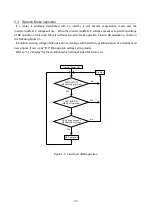
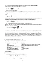
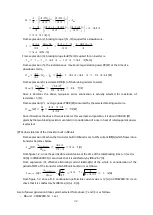
Dynamic Brake operation


If  a  motor  is  suddenly  decelerated  with  an  inverter,  it  will  become  regeneration  mode  and  the 

inverter-middle D.C. voltage will rise.


When the inverter-middle D.C. voltage exceeds set-up starting voltage 

of DB operation at this time, DB unit performs Dynamic brake operation. Flow to DB operation is shown in 

the following figure 5.5. 

  In addition, starting voltage of DB operation and voltage width which stops DB operation of a statement all 

over a figure, It sets up by "F10" (DB operation voltage setting mode).   

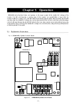
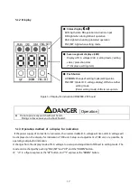
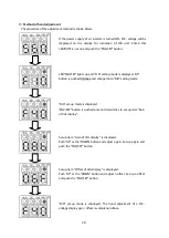
Refer to "5.1.2 Display" for the conditions which various kinds of LED turns on. 


LED

86A

OFF

(DB Unit unprotection)

Inverter Power ON

DB Stop

Yes

No

Yes

No

Yes

No

LED

RUN

ON

(DB Unit Operation)

DC Voltage exceeds 

DB Operation voltage

DB Operation


Figure 5.5    Flow chart of DB operation 


Содержание VFDB2009 Series

Страница 1: ...VFDB2009 Operation Manual...

Страница 2: ...ke unit For correct use please carefully read this instruction manual prior to using the VFDB2009 series dynamic brake unit In order to accommodate the many special functions to a wide variety of appl...

Страница 3: ...DB unit is an open structure it is put into panel and it is carried out as a turning on electricity part Failure to do so may cause an electric shock Do not carry with the option cover Doing so may l...

Страница 4: ...from confirmation of stop of motor Also check DC voltage between P to N and confirm that it is less than 30V Failure to do so may cause an electric shock personal injury or fire Unauthorized persons...

Страница 5: ...ion or Master Slave system paralle operation 21 5 3 DYNAMIC BRAKE OPERATION 22 5 4 SET UP ITEMS 23 5 4 1 List of set up items 23 5 4 2 F10 Setting mode of DB operation voltage 23 5 4 3 F20 Power suppl...

Страница 6: ...ime of communication option PC board attachment 43 7 1 7 Set up of the inverter at the time of communication option PC board use 45 7 2 OPTION COVER 45 CHAPTER 8 REPLACEMENT WITH THE OLD MODEL DB UNIT...

Страница 7: ...DB2009 dinamic brake system is designed so that the content of a lead mercury cadmium sexavalent chrome PBB and PBDE may be based on the RoHS instructions which EU defines in consideration of the infl...

Страница 8: ...ou intend to use the product stated in this document for special purposes such as passenger cars medical devices aerospace devices nuclear energy controls and submarine relaying machines or systems co...

Страница 9: ...ation 0 50 Preservation temperature 20 60 Humidity 20 90 Not condensation Altitude 1000m or less Atmosphere No poisonous gas metal powder and oil and fat etc Protection structure IP00 JIS C 0920 EN IE...

Страница 10: ...unit To use dynamic brake unit installed in a control panel install as follows DANGER Mounting Improper installation may cause an electric shock or a fire 1 Installation direction VFDB2009 DB unit tu...

Страница 11: ...rformed DB operation detection and carried out DB operation detection previously and takes out instructions of ON OFF of switching device IGBT to other parallel units Figure 3 3 shows the connection m...

Страница 12: ...n 52MAX M U VW SHT OCRY MCCB MC R S T 52 MAX 1 2 1 2 3 4 5 6 8 9 7 P PR N OCRY DBR CN 2 CN 3 400 V 200 V TH 8 8 8 TB 2 DB _IN DB _ ON 86 A 52 MA 1 2 3 4 5 6 8 9 7 P PR N OCRY DBR CN 2 CN 3 400 V 200 V...

Страница 13: ...otection coordination in thermal relay OCRY It becomes a cause of a fire when cooperation cannot be taken About selection of braking resistor DBR and thermal relay OCRY refer to 6 2 Selection of braki...

Страница 14: ...al relay OCRY connection Connect the inverter middle D C voltage 2 Connect a braking resistor Connect the thermal relay OCRY PR For DBR connection Connect a braking resistor N DC voltage input side Fo...

Страница 15: ...ght 4kg DBIF2009 Z Option used DBIF2009 Z Option used Cover Option 4 M5 Mouting Hole Cover Option Option Space Treminal marking Terminal screws PR N P M4 VFDB2009 Z TB2 M3 Treminal marking Terminal sc...

Страница 16: ...er and it rises up to the voltage set to the DB operating point and LED DB lights At this time brake resistor connected to DB unit consumes regeneration energy and if inverter middle D C voltage turns...

Страница 17: ...seconds while the VFDB2009 Z board is operating normally While not blinking failure of the loose connection of CN1 or a VFDB2009 Z board can be considered 3 The middle D C voltage of an inverter turns...

Страница 18: ...the display mode of D C voltage to a setup and adjustment of DBunit to setting mode The mode can be changed by pushing FNC SET and UP and the DOWN button in a figure expresses the UP button and expre...

Страница 19: ...ET button is pushed during the display of direct current voltage it will shift to setting mode F10 and LED FNC SET will light up simultaneously If UP or the DOWN button is pushed into setting mode it...

Страница 20: ...plication 5 2 1 Change of a power supply voltage Before turing on the power supply of an inverter please switch connector CN2 and CN3 of VFDB2009 Z PC board according to the power supply voltage of th...

Страница 21: ...is turned ON D C voltage will be displayed on the display for indication of DB unit Check that LED RUN is not on and push the FNC SET button LED FNC SET lights up and F10 setting mode is displayed UP...

Страница 22: ...ode for the details of a setting item Set up item power supply voltage selection of F20 set up mode is displayed by the same operation as 5 2 1 Change of power supply voltage FNC SET button is pushed...

Страница 23: ...to DB operation is shown in the following figure 5 5 In addition starting voltage of DB operation and voltage width which stops DB operation of a statement all over a figure It sets up by F10 DB oper...

Страница 24: ...at the time of shipment a preset value may differ from an initial value 4 The display gain offset automatic adjustment mode of D C voltage is possible only at 400V series 5 4 2 F10 Setting mode of DB...

Страница 25: ...ge falls or more 36 V from 720V DB operation is stopped 5 4 3 F20 Power supply voltage selection Master Slave selection Station number set up mode In F20 set up mode a setup of a power supply voltage...

Страница 26: ...eries Master unit cF0 Slave unit Cf1 Station number set up It sets up when using Communication option board DBIF2009 Z Certainly setting up a station number setup sequentially from 1 and 7 does not se...

Страница 27: ...Table 5 6 F30 set up items No Set up items Set up range Initial value 1 Automatic calculation of Vdc is possible cc0 Automatic calculation stop cc1 Automatic calculation start cc0 2 Vdc automatic calc...

Страница 28: ...ts of the triple figures When you adjust display gain offset of D C voltage automatically please change a setup into cc1 and push the FNC SET button Change of a set up is made with UP or the DOWN butt...

Страница 29: ...hed 3 times and changed into F40 setting mode F40 set up mode is displayed FNC SET button is pushed once and it switches to set up item Gain of Vdc display Set up item Gain of Vdc display is displayed...

Страница 30: ...re 6 1 DB operating time chart 6 1 2 Current value which the transistor built in DBunit permits At the time of DB operation please select a braking resistor so that the current exceeding the character...

Страница 31: ...sec the regeneration energy E J and a necessary deceleration Braking torque N m are shown by the next expression Regenation energy 1 Braking torque 2 However 3 GD2 Flywheel effect M Motor efficiency H...

Страница 32: ...3 permissible current value of DB unit current indicated by type of DB unit When not installing on the permissible current value the braking resistance is enlarged and the current that flows to the DB...

Страница 33: ...l in consideration of a rise in heat of rated apparent power is selected The dosis tplarate of the transistor built in DBunit From expression 8 when the transistor built in DBunit is set to ON current...

Страница 34: ...y is shown in the following table Table 6 1 Example of selection Inverter power source voltage Brake resistor Thermal relay Maximum braking power kW Peak current A DB unit type Type Setting value A 20...

Страница 35: ...ommunication option PC board The following functions are added by using communication option PC board DBIF2009 Z Adjustment of the display gain offset of D C voltage becomes unnecessary In order to ma...

Страница 36: ...selection is possible Refer to 7 1 7 Set up of the inverter at the time of communication option PC board use for details Moreover a up rank unit sequencer can be told about failure of DB unit via an i...

Страница 37: ...unit main part by the following methods The metal thread part of an attached spacer BMP 310E is attached to a total of four holes in the left hand side side part of DB unit main part Please also atta...

Страница 38: ...37 DBIF2009 Z board is attached to the spacer attached by with the screw of M3 DBIF2009 Z PC board Figure 7 3 DBIF2009 Z PC board attachment...

Страница 39: ...e latter DB unit side between DB unit and DB unit DBIF2009 Z PCB VF66B inverter 30kW or more VFDB2009 Z PCB 1 4 1 5 1 6 ON CN1 1 4 CN2 CN3 CN1 SW1 CN6 2 turns or more core Figure 7 4 Connection and te...

Страница 40: ...The connector by the side of 6 pins of an attached cable is connected with connector CN6 of a VFDB2009 Z board When DB unit is connected in parallel please make connection between each attached cable...

Страница 41: ...ide Housing DF1E 4S 2 5C Hirose 1 Terminal DF1B 2022SCA or DF1B 2022SCFA Hirose 4 Gilding processing article Cable Cable CO SPEV SB A 2Px0 5SQLF Hitachi cable 1 Recommendation 1 An equivalent article...

Страница 42: ...er In the case of the parallel operation of DB unit the telecommunication cable which connects a DBIF2009 Z board and a DBIF2009 Z board is required The cable is not attached Please manufacture a conn...

Страница 43: ...en DBIF2009 Z PC board and DBIF2009 Z PC board Terminator switch SW1 on a DBIF2009 Z board is switched If a switch is moved to the ON side it will become Switch ON and it will become Switch OFF if it...

Страница 44: ...up of single operation or Master Slave system operation are referred to Please perform various setup Single operation 1 2 3 4 5 6 8 9 7 P PR N OCRY DBR CN 2 CN 3 400 V 200 V TH 8 8 8 SHT OCRY 52 MAX M...

Страница 45: ...SIGNAL D C Busbar DB Unit DB Voltage DC DC Converter Slave Master Protection DB Operation DB Unit DB Voltage DC DC Converter Slave Master Protection DB Operation Core 2turns or more Core 2turns or mo...

Страница 46: ...verter is continued When J 15 is negative J 15 0 in the case of the protection mode of DB unit it is displayed on the display for indication of an inverter as dbO O numerical value of station number a...

Страница 47: ...uctions manual of VFDB2002 series Table 8 1 Old and new DB unit compatible table Built in transistor permissible current Cooling system Old DB unit Alternative DB unit 50A Natural cooling VFDB2002 50...

Страница 48: ...case of the parallel operation of VFDB2009 series and VFDB2002 series it connects like Figure 8 1 52MAX M U V W SHT OCRY MCCB MC R S T 52MAX 1 2 1 2 3 4 5 6 8 9 7 P PR N OCRY DBR CN2 CN3 400V 200V TH...

Страница 49: ...nd wire for wiring If the twist line is not used the surge voltage is by the twice or more there is a possibility of damaging the unit 4 Refer to Table 3 1 of 3 2 connection for the size of the use ca...

Страница 50: ...9 2 List of trouble shootng Protect display Cause Measure FF1 A braking resistor is un connecting A braking resistor is connected between P and PR IGBT breaks down DB unit is exchanged Each of power s...

Страница 51: ...of FF3 Initialize a preset value according to the following procedures Pushing each button of UP DOWN and FNC SET is continued simultaneously The button of DOWN and FNC SET is detached in the state wh...

Страница 52: ...her operation is continued for an inverter in protection mode or it stops Refer to 7 1 7 Set up of the inverter at the time of communication option PC board use for the change method In the protection...

Страница 53: ...er source is turned OFF and 10 minutes or more pass In addition check voltage between P and N and check it is 30V or less Failure to do so may cause an electric shock Do not perform maintenance and in...

Страница 54: ...enki co jp HEAD OFFICE Tokyo TatemonoYaesu Bldg 1 4 16Yaesu Chuo ku Tokyo Japan ZIPCODE103 0028 TEL 81 3 5202 8132 6 FAX 81 3 5202 8150 Contents of this manual are subject to change without notice 201...

Отзывы: