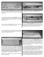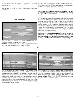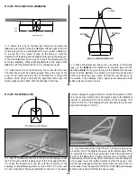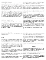
the hinges to keep them centered. Close the hinge gap to 1/32"
or less – it is better to have a
slight gap to avoid inadvertently
gluing the control surfaces together. Remove the pins if you have
used any.
❍
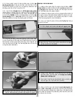
4. Add 6 drops of thin CA to the center of all the hinges on
both the top and the bottom.
❍
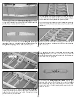
5. Join the rudder to the fin using the same procedures.
❍
6. Clean the aileron torque rod arms with rubbing alcohol to
remove skin oils or smeared petroleum jelly.
❍
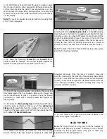
7. Prepare the hinge slots in the ailerons the same way as the
tail surfaces.
❍
8. Use a toothpick to pack the torque rod holes in the ailerons
with 30-minute epoxy, then install the ailerons with the hinges and
thin CA using the methods we’ve described. Wipe away the epoxy
that is squeezed out of the ailerons with a paper towel and alcohol.
Do not use accelerator on any of the hinges. Do not glue the
hinges with anything but thin CA and do not attempt to glue
one half of the hinge at a time with medium or thick CA. They
will not be properly secured and the controls could separate
while the model is in flight.
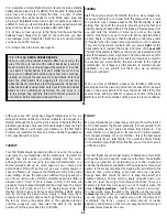
THE CA WICKS
ALONG THE "TUNNELS"
TO THE ENTIRE
HINGE SURFACE
ASSEMBLE, THEN APPLY 6 DROPS
OF THIN CA TO CENTER
OF HINGE, ON BOTH SIDES
45
FINAL CONTROL HOOKUPS
❍
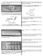
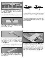
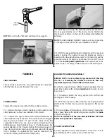
1. Install the Elevator and Rudder small nylon control horns in
line with the pushrod exits as shown on the plans. Hold the horns
in position and mark the location of the mounting holes. Drill
3/32" mounting holes through the marks. Wick two to three drops
of Thin CA into the holes to harden the underlying balsa. The
horns are screwed in place using 2-56 x 5/8" machine screws and
nylon nut plates. Do not tighten the screws as to crush the
underlying balsa.
❍
2. Mount the servos into the main servo tray oriented as shown
on the fuselage plan top view. Mount the aileron servo in the
aileron tray. Since the main servo tray is adjustable fore and aft
for small CG corrections, do not glue it in until told to do so.
❍
3. For easy setup and good control response, we recommend
you start off using servo horns resembling those on the plans. The
Rudder, Throttle and Elevator horns are made using the large four
armed horns. The aileron servo used the smaller, six armed horn
to provide differential throw. In this case it will cause the ailerons
to deflect “up” more than the deflect “down.”
❍
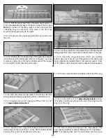
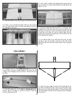
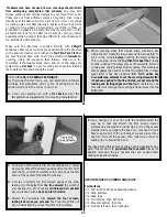
4. Make the Rudder and Elevator pushrods: (Use the sketch on
the plans to assist in making the pushrods. Both the Elevator and
Rudder are made using the same sketch.)
A. Locate the two 36" threaded rods. Cut each of the threaded
rods so there are two 10" rods with threads on one end. Save
the remaining wire, as it will be used in a couple of minutes.
B. Locate the two 1/4" x 16" hardwood dowels. Cut them to a
length of 14". Drill a 5/64" hole 1" from the end of the dowel.
A total of four holes need to be drilled.
C. Using a sharp hobby knife, cut a notch from the hole to the
end of the dowel as was done with the ailerons to provide
access for the torque rods.
D. Bend one end of the threaded rods, and one end of the
remaining wire, 1/4" from the non-threaded end. Insert the
bend into the hole drilled in the dowel.
46

