


Controller functions
RES-409
Page 43
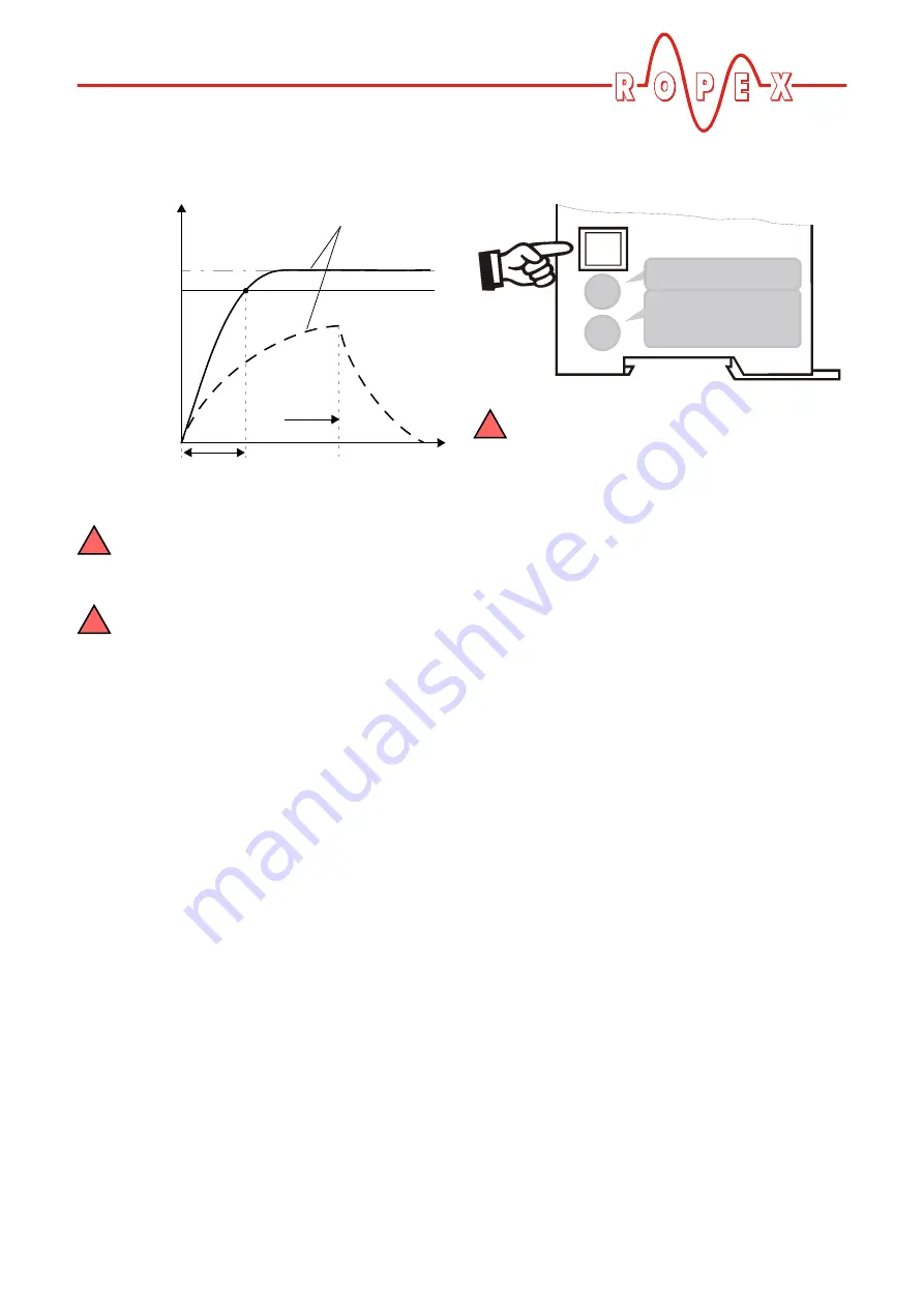
(304) is indicated and the fault relay is switched
(
section 10.16 "Error messages" on page 45).
The heatup timeout cannot be started with
the 24VDC START 1 signal. This signal has
no function here.
The heatup timeout must be activated either
in the ROPEX visualization software
(
section 10.12 "Diagnostic interface /
visualization software (as of February 2007)" on
page 43) or via the CAN interface (CAN message
address 11) (default setting: heatup timeout off).
10.12
Diagnostic interface / visualization
software (as of February 2007)
An interface with a 6-pole Western socket is provided
for system diagnostics and process visualization. This
interface allows a data connection to be set up to the
ROPEX visualization software using the ROPEX
CI-USB-1 communication interface.
Only a ROPEX communication interface is
allowed to be connected to the diagnostic
interface. Connecting another device (e.g. a
telephone cable) could result in malfunctions or
damage to the controller.
The ROPEX visualization software is described in a
separate document.
10.13
Booster connection
All controllers manufactured up to January 2007 only
have an optional connection for an external switching
amplifier (booster) (
(MODs)" on page 7). Modification 26 (MOD 26) must
be installed in the controller for this purpose.
A booster connection is provided as standard on all
RES-409 controllers manufactured as of February
2007.
This connection (at terminals 15+16) is necessary for
high primary currents (continuous current > 5A, pulsed
current > 25A). The switching amplifier should be wired
as described in section 8.7 "Wiring diagram with
booster connection (MOD 26)" on page 16.
Set
95% of Set
ACTUAL temp.
Time
Heatup time
Fault
304
Time-
out
!
!
0
5
1 2
3
4
6
7
8
9
DIA
G
!


