Reference Information
2-2
Toshiba
11
PREPARATION
VHF UHF
VHF/UHF
L
R
CH
OUT (
TO TV)
IN
(
FROM ANT.)
LINE
OUT
LINE
IN 1
VIDEO
AUDIO
34
RF
OUT
(
TO TV)
IN
(
FROM ANT.)
RF
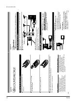
Antenna/VCR/TV Connection
1
Disconnect the antenna cable from your
TV and connect it to the
RF IN
terminal on the
VCR.
2
Connect the
RF OUT
terminal to the
TV
.
AUDIO/VIDEO Connections
The
AUDIO/VIDEO jacks are also available to connect your
TV
.
When connected your TV using the
AUDIO/VIDEO OUT jacks
T
o
watch video pictures, set the video input mode
on your
TV
. For the video input mode, refer to
the manual of your
TV
.
Setting the VCR Output Channel
When the VCR is connected in this way, the VCR sends the output
signals to channel 3 or 4 on your TV. Set the output channel
selector (CH selector) of the VCR to “3” or “4”, whichever is vacant
in your area.
VHF/UHF
combinaion antenna
VHF antenna
only
UHF antenna
only
Antenna splitter
(not supplied)
1
2
Connections
Before you use this VCR, it is necessary to connect it to your TV. Several ways of connecting are
available depending on your use of TV or cable box. Select one which is applicable to your equipment.
PREP
ARA
TION
L
R
CH
OUT
(TO TV)
IN
(FROM ANT.)
LINE
OUT
LINE
IN 1
VIDEO
AUDIO
34
RF
LINE OUT VIDEO
VIDEO IN
AUDIO IN
LINE OUT AUDIO
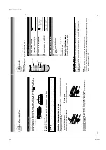
Cable Connection
Choose one of the below according to your usage of the cable box.
This set-up will enable you to:
–
record an unscrambled channel.
–
watch an unscrambled channel while recording it.
–
record an unscrambled channel while watching
another (only when you connect a cable-
compatible TV).
You will need to:
•
select
TV channel 3 or 4 to receive video signals.
•
to record a channel while watching another
, press
TV/VCR
on the remote control to turn of
f the
“VCR” indicator in the VCR display and select a
desired channel on the
TV (only when you connect
a cable-compatible
TV).
L
R
CH
OUT
(TO TV)
IN
(FROM ANT.)
LINE
OUT
LINE
IN 1
VIDEO
AUDIO
34
RF
Incoming cable
10
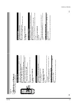
Setting up the Remote Contr
ol
1
Open the battery compartment lid on the
rear panel.
2
Install 2 batteries (
“AA
” size) following
the polarity diagrams.
3
Close the battery compartment lid.
4
Point the remote control at the VCR and press the buttons within the operating range.
Distance: within about 7 m from the front of the remote sensor
Angles: within about 30
˚ in every direction
Notes on batteries
•
The life of the batteries is about 1 year
depending on the conditions of use.
•
If the remote control does not operate
correctly
, replace all batteries with new ones.
•
If the remote control is not to be used for a
long period of time, remove the batteries to
avoid possible damage from battery corrosion.
Caring for the r
emote contr
ol
•
Do not expose the remote sensor of the VCR
to a strong light source such as direct sunlight
or illumination (especially high-frequency
lighting) when using the remote control.
•
Be careful not to spill water on the remote
control or to place it on anything wet, and avoid
sharp impacts.
Ho
w to Use the Remote Control
This section explains how to get ready for remote control operation.
PREP
ARA
TION
+
+
Содержание W603C
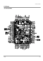
Страница 20: ...Reference Information Toshiba 2 13 2 2 1 IC301 LA71072M 2 2 IC Blocks ...
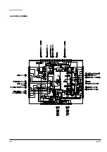
Страница 21: ...Reference Information 2 14 Toshiba 2 2 2 IC501 AN3662 ...
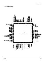
Страница 22: ...Reference Information Toshiba 2 15 2 2 3 IC601 MN101D02X ...
Страница 23: ...Reference Information 2 16 Toshiba MEMO ...
Страница 25: ...Product Specifications 3 2 Toshiba MEMO ...
Страница 56: ...Alignment and Adjustment Toshiba 5 11 Fig 5 21 Main PCB Top View VR501 Location for VR501 ...
Страница 57: ...5 12 Toshiba Alignment and Adjustment MEMO ...
Страница 59: ...Exploded View 6 2 Toshiba 6 1 Packing Assembly A702 A701 A702 Y101 Y102 UT01 ...
Страница 63: ...Exploded View 6 6 Toshiba MEMO ...
Страница 73: ...Replacement Parts List 7 10 Toshiba MEMO ...
Страница 74: ...Toshiba 8 1 8 Block Diagram ...
Страница 75: ...Block Diagram 8 2 Toshiba MEMO ...
Страница 76: ...Toshiba 9 1 9 PCB Diagrams 9 2 9 3 9 3 9 3 9 1 Main 9 2 VFD 9 3 Jack 9 4 Key ...
Страница 77: ...PCB Diagrams 9 2 Toshiba 9 1 Main ...
Страница 78: ...PCB Diagrams Toshiba 9 3 9 2 VFD 9 3 Jack 9 4 Key ...
Страница 79: ...PCB Diagrams 9 4 Toshiba MEMO ...
Страница 82: ...Schematic Diagrams Toshiba 10 3 10 1 S M P S Power ...
Страница 83: ...Schematic Diagrams 10 4 Toshiba IC601 VFD 10 2 Logic ...
Страница 85: ...Schematic Diagrams 10 6 Toshiba 10 3 A V ...
Страница 87: ...Schematic Diagrams 10 8 Toshiba 10 4 Hi Fi MTS ...
Страница 89: ...Schematic Diagrams 10 10 Toshiba 10 5 TM Block Input Ouput ...
Страница 90: ...Schematic Diagrams Toshiba 10 11 10 6 VFD ...
Страница 91: ...Schematic Diagrams 10 12 Toshiba 10 7 Remote Control ...


