Alignment and Adjustment
Toshiba
5-9
5-3 Head Switching Point Adjustment
1) Playback the alignment tape.
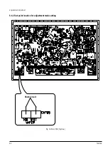
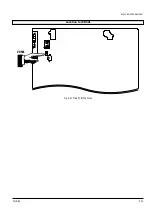
2) Intermittently short-circuit the two test points on Main PCB to set the adjustment mode. (See Fig. 5-2)
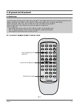
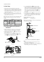
3) Press the “SP/SLP” button of remote control then adjustment is operated automatically. (See Fig. 5-1)
4) Turn the Power off.
5-4 NVRAM Option Setting
1) Intermittently short-circuit the two test points on Main PCB to set the adjustment mode. (See Fig. 5-2)
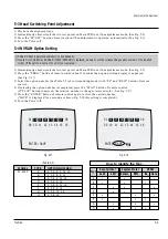
2) Press the “PROG.” button of remote control about 5 seconds then option setting display is appeared.
(See Fig. 5-17)
3) Select the option number (See Table 5-2) of corresponding model with “FF” and “REW” button of remote
control.
4) If selecting the option number is completed, press the “PLAY” button of remote control.
(If “PLAY” button is pressed, the selected number is changes reversed color. ; See Fig. 5-17)
5) Press the “ENTER” button of remote control again to store the option number.
(“SAVE” is displayed for a second as shown Fig. 5-18 this setting is completed.)
6) Turn the Power off.
1) NVRAM Option is adjusted at production line basically.
2) In case Micom (IC601) and NVRAM (IC603 ; EEPROM) is replaced, be sure to set the corresponding ooption number of the repaired
model. (If the option is not set, the unit is not operated.)
ENTER : SAVE
01
02 03 04 05 06 07
08
09 10 11 12 13 14 15 16
Fig. 5-17
ENTER : SAVE
01
02 03 04 05 06 07
08
09 10 11 12 13 14 15 16
Fig. 5-18
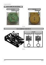
How to identify the Type
Type
Assy-Cylinder
Capstan Motor VR501
ALPS
SEM
Sankyo
SEM
Be
None
A
•
•
•
B
•
•
•
C
•
•
•
D
•
•
•
E
•
•
•
F
•
•
•
G
•
•
•
H
•
•
•
MODEL
TYPE
OPTION NUMBER
W-603C
A
2, 3, 6, 8, 9, 12, 16
B
2, 3, 6, 8, 9, 12
C
2, 3, 6, 8, 12, 16
D
2, 3, 6, 8, 12
E
2, 3, 6, 9, 12, 16
F
2, 3, 6, 9, 12
G
2, 3, 6, 12, 16
H
2, 3, 6, 12
<Table 5-2>
Содержание W603C
Страница 20: ...Reference Information Toshiba 2 13 2 2 1 IC301 LA71072M 2 2 IC Blocks ...
Страница 21: ...Reference Information 2 14 Toshiba 2 2 2 IC501 AN3662 ...
Страница 22: ...Reference Information Toshiba 2 15 2 2 3 IC601 MN101D02X ...
Страница 23: ...Reference Information 2 16 Toshiba MEMO ...
Страница 25: ...Product Specifications 3 2 Toshiba MEMO ...
Страница 56: ...Alignment and Adjustment Toshiba 5 11 Fig 5 21 Main PCB Top View VR501 Location for VR501 ...
Страница 57: ...5 12 Toshiba Alignment and Adjustment MEMO ...
Страница 59: ...Exploded View 6 2 Toshiba 6 1 Packing Assembly A702 A701 A702 Y101 Y102 UT01 ...
Страница 63: ...Exploded View 6 6 Toshiba MEMO ...
Страница 73: ...Replacement Parts List 7 10 Toshiba MEMO ...
Страница 74: ...Toshiba 8 1 8 Block Diagram ...
Страница 75: ...Block Diagram 8 2 Toshiba MEMO ...
Страница 76: ...Toshiba 9 1 9 PCB Diagrams 9 2 9 3 9 3 9 3 9 1 Main 9 2 VFD 9 3 Jack 9 4 Key ...
Страница 77: ...PCB Diagrams 9 2 Toshiba 9 1 Main ...
Страница 78: ...PCB Diagrams Toshiba 9 3 9 2 VFD 9 3 Jack 9 4 Key ...
Страница 79: ...PCB Diagrams 9 4 Toshiba MEMO ...
Страница 82: ...Schematic Diagrams Toshiba 10 3 10 1 S M P S Power ...
Страница 83: ...Schematic Diagrams 10 4 Toshiba IC601 VFD 10 2 Logic ...
Страница 85: ...Schematic Diagrams 10 6 Toshiba 10 3 A V ...
Страница 87: ...Schematic Diagrams 10 8 Toshiba 10 4 Hi Fi MTS ...
Страница 89: ...Schematic Diagrams 10 10 Toshiba 10 5 TM Block Input Ouput ...
Страница 90: ...Schematic Diagrams Toshiba 10 11 10 6 VFD ...
Страница 91: ...Schematic Diagrams 10 12 Toshiba 10 7 Remote Control ...


