


Disassembly and Reassembly
Toshiba
4-9
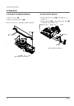
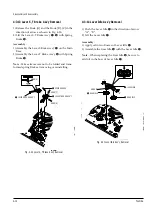
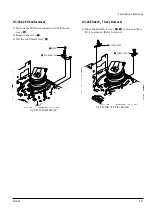
4-3-7 Assembly of Gear FL Cam, Gear Joint 1, 2
1) Be sure to align dot mark of Gear Joint 1
Œ
with
dot mark of Gear Joint 2
´
as shown Fig. 4-14
(Refer to Timing Point 1), confirm the Timing Point
2 of the Gear Joint 2
´
and Slider Cam
ˇ
.
2) Align the Gear FL Cam
¨
with the Gear Worm
Wheel Post as shown detail drawing. (Refer to
Timing Point 3)
Œ
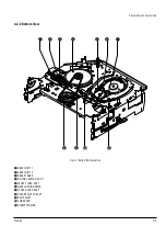
GEAR JOINT 1
´
GEAR JOINT 2
ˇ
SLIDER CAM
TIMING POINT 1
¨
GEAR FL CAM
GEAR WORM WHEEL
POST
TIMING POINT 2
TIMING POINT 3
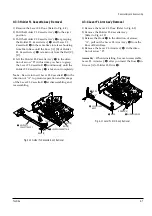
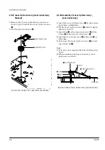
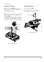
4-3-8 Holder Worm, Gear Worm, Gear Worm
Wheel Removal
1) Release the Hook [A] in the direction of arrow and,
remove the Holder Worm
Œ
.
2) Remove the Gear Worm
´
.
3) Remove the Gear Worm Wheel
ˇ
. (After remov-
ing the Gear FL Cam as shown Fig. 4-13)
Note
: Secure the Hook [A] after installing the Holder
Worm
Œ
.
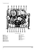
Œ
HOLDER WORM
´
GEAR WORM
HOOK [A]
ˇ
GEAR WORM WHEEL
Fig. 4-14 Assembly of Gear FL Cam, Gear Joint 1, 2
Fig. 4-15 Holder Worm, Gear Worm, Gear Worm Wheel Removal
Содержание W603C
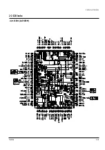
Страница 20: ...Reference Information Toshiba 2 13 2 2 1 IC301 LA71072M 2 2 IC Blocks ...
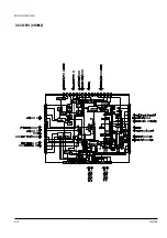
Страница 21: ...Reference Information 2 14 Toshiba 2 2 2 IC501 AN3662 ...
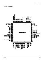
Страница 22: ...Reference Information Toshiba 2 15 2 2 3 IC601 MN101D02X ...
Страница 23: ...Reference Information 2 16 Toshiba MEMO ...
Страница 25: ...Product Specifications 3 2 Toshiba MEMO ...
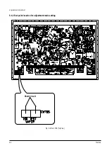
Страница 56: ...Alignment and Adjustment Toshiba 5 11 Fig 5 21 Main PCB Top View VR501 Location for VR501 ...
Страница 57: ...5 12 Toshiba Alignment and Adjustment MEMO ...
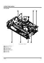
Страница 59: ...Exploded View 6 2 Toshiba 6 1 Packing Assembly A702 A701 A702 Y101 Y102 UT01 ...
Страница 63: ...Exploded View 6 6 Toshiba MEMO ...
Страница 73: ...Replacement Parts List 7 10 Toshiba MEMO ...
Страница 74: ...Toshiba 8 1 8 Block Diagram ...
Страница 75: ...Block Diagram 8 2 Toshiba MEMO ...
Страница 76: ...Toshiba 9 1 9 PCB Diagrams 9 2 9 3 9 3 9 3 9 1 Main 9 2 VFD 9 3 Jack 9 4 Key ...
Страница 77: ...PCB Diagrams 9 2 Toshiba 9 1 Main ...
Страница 78: ...PCB Diagrams Toshiba 9 3 9 2 VFD 9 3 Jack 9 4 Key ...
Страница 79: ...PCB Diagrams 9 4 Toshiba MEMO ...
Страница 82: ...Schematic Diagrams Toshiba 10 3 10 1 S M P S Power ...
Страница 83: ...Schematic Diagrams 10 4 Toshiba IC601 VFD 10 2 Logic ...
Страница 85: ...Schematic Diagrams 10 6 Toshiba 10 3 A V ...
Страница 87: ...Schematic Diagrams 10 8 Toshiba 10 4 Hi Fi MTS ...
Страница 89: ...Schematic Diagrams 10 10 Toshiba 10 5 TM Block Input Ouput ...
Страница 90: ...Schematic Diagrams Toshiba 10 11 10 6 VFD ...
Страница 91: ...Schematic Diagrams 10 12 Toshiba 10 7 Remote Control ...


