background image

APPENDIX 1 SPECIFICATIONS 

EO1-33029 

A1.3 Media


A1- 3 

A1.3.1  Media Type (Cont.) 


[Unit: mm] 

Label dispensing mode 

Item 

Batch mode 

Cut mode 

Label: 38.0 

c


Minimum media pitch 

15.0  

Tag: 25.4  

d


Label length 

Min. 12.5  

Min. 32.0  

e


Width including backing paper 

100.0- 242.0 

100.0 – 235.0 

f

 Gap length 

2.5 – 20.0 

6.0 – 20.0 

g


Black mark length (Tag paper) 

2.0 – 10.0 

h


Effective print width 

216.8

±

0.2 

i


Print speed up/slow down area 

1.0 

j


Black mark length (Label) 

Refer to NOTE 3 below. 

Max. print length 

640.0 

Maximum effective length for on the fly issue 

320.0 

Max. outer roll diameter 

φ

230  

Label + backing paper 

0.13 – 0.18 

Thickness 

Tag 

0.08 – 0.18 


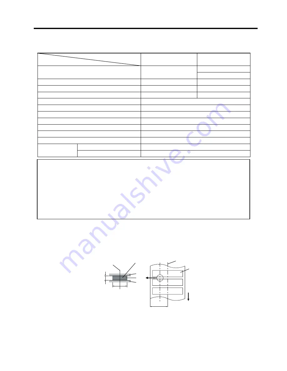
A1.3.2  Detection Area of the Transmissive Sensor 

The transmissive sensor is movable from the center to the left edge of media.   
The transmissive sensor detects a gap between labels, as illustrated below. 


NOTES: 

1.  To ensure print quality and print head life use only TOSHIBA TEC specified media. 
2.  When using the cutter ensure that label length 

d

 plus inter-label gap length 

f

 exceeds 38 mm.  

 (i.e. label pitch should be greater than 38 mm.) 

3.  When requesting black marks on label rolls, the following requirements must be satisfied. 
 

When the gap length is less than 4 mm: 


The black mark length should be longer than the gap length. 


When the gap length is 4 mm or more: 


The black mark should not overlap the gap for more than 4 mm or the following label. 

4.  “On the fly issue” means that the printer can feed and print without stopping between labels. 


Sensor position 

Area to be detected. 

Center of media 

Print side  

Min. 12 mm 

Label 
Gap 
Label 

Min. 2.0 mm 

(Min. 6.0 mm when using 

the  cutter module.) 

Sensor is movable 
within this range. 

Media feed direction 

Содержание TEC B-852-TS12-QQ

Страница 1: ...TEC Label Tag Printer B 852 TS12 QQ Owner s Manual ...

Страница 2: ... brouilleur du Canada for CANADA only Copyright 2002 by TOSHIBA TEC CORPORATION All Rights Reserved 570 Ohito Ohito cho Tagata gun Shizuoka ken JAPAN HP PCL5 is a registered trademark of Hewlett Packard Corporation Centronics is a registered trademark of Centronics Data Computer Corp Microsoft is a registered trademark of Microsoft Corporation Windows is a trademark of Microsoft Corporation As an ...

Страница 3: ...g with wet hands as this may cause electric shock If the machines share the same outlet with any other electrical appliances which consume large amounts of power the voltage will fluctuate widely each time these appliances operate Be sure to provide an exclusive outlet for the machine as this may cause the machines to malfunction Do not place metal objects or water filled containers such as flower...

Страница 4: ...t high temperatures high humidity dust or gas Ensure the printer is operated on a level surface Any data stored in the memory of the printer could be lost during a printer fault Try to avoid using this equipment on the same power supply as high voltage equipment or equipment likely to cause mains interference Unplug the machine whenever you are working inside it or cleaning it Keep your work envir...

Страница 5: ...the Supply Holder onto the Supply Holder Frame 2 9 2 7 3 Loading Media into the Printer 2 9 2 8 Setting Sensor Positions 2 12 2 8 1 Setting the Feed Gap Sensor 2 12 2 8 2 Setting the Black Mark Sensor 2 12 2 9 Loading the Ribbon 2 13 2 10 Inserting the Optional PCMCIA Cards 2 14 2 11 Test Print 2 15 3 PRINTER OPERATION 3 1 3 1 Overview 3 1 3 2 Operating Modes 3 1 3 3 Installing the Printer Drivers...

Страница 6: ...A1 4 A1 4 Ribbon A1 5 APPENDIX 2 MESSAGE AND LED A2 1 APPENDIX 3 INTERFACE A3 1 APPENDIX 4 SYSTEM MODE A4 1 A4 1 Operation Panel A4 1 A4 2 Overview A4 2 A4 3 Self Diagnostic Test A4 3 A4 4 Printer Parameter Fine Adjustment A4 5 A4 5 Test Print A4 13 A4 6 PCL Emulation Setting A4 19 A4 7 Additional Information A4 23 A4 7 1 Self Diagnostic Test Result Sample and Descriptions A4 23 A4 7 2 Maintenance...

Страница 7: ...dia can be used since the black mark sensors are located above and under the media passage respectively and the media sensors can be moved from the center to the left edge of the media When the optional interface board is installed Web functions such as remote maintenance and other advanced network functions are available Superior hardware including the specially developed 300 dots inch 11 8 dots ...

Страница 8: ...Holder Frame L 1 pc P No FMED0035201 Supply Holder Base 1 pc P No FMBB0063401 Power Cord 1 pc P No FBCB0030202 Supply Holder Unit 1 pc P No FMBD0042701 Supply Holder Frame R 1 pc P No FMED0035301 Wing Bolt M 4x6 2 pcs P No X20L406130 CAUTION Be sure to use TOSHIBA TEC approved print head cleaner Failure to do this may shorten the print head life TOSHIBA TEC CORPORATION TEC Label Tag Printer B 850 ...

Страница 9: ...l Cutter Module is installed on the printer Dimensions in inches mm 16 9 429 16 8 427 7 1 181 9 6 243 10 4 265 15 2 385 LCD Message Display Operation Panel Power Switch Media Outlet Top Cover Supply Holder Frame Supply Holder Unit Expansion I O Interface Connector Option Parallel Interface Connector Centronics Serial Interface Connector RS 232C Keyboard Interface Connector PCMCIA Card Slot Option ...

Страница 10: ... 4 1 for further information about the Operation Panel LCD Message Display ON LINE LED Green ERROR LED Red PAUSE key POWER LED Green FEED key RESTART key FEED RESTART PAUSE POWER ON LINE ERROR Print Head Print Head Block Head Block Release Lever Ribbon Holder Paper Guide Black Mark Feed Gap Sensor Platen ...

Страница 11: ...pen Be careful not to allow fingers or articles of clothing to get caught into any of the moving parts of the printer especially the optional cutter mechanism Make sure to turn off the printer power and to remove the power cord from the printer whenever working on the inside of the printer such as changing the ribbon or loading the media or when cleaning the printer For best results and longer pri...

Страница 12: ...eed Gap Sensor or Black Mark Sensor depending on the media being used Refer to Section 2 8 8 Load the ribbon into the Print Head Block Refer to Section 2 9 9 Turn the Power ON Refer to Section 2 6 10 Perform a test print Refer to Section 2 11 11 Install the Printer Drivers Refer to Section 3 NOTE Use of a Windows Driver will allow issuing media on the B 852 printer in place of a general laser prin...

Страница 13: ...X6 Wing Bolts supplied as shown below 2 Attach the assembled Supply Holder Frame to the rear of the B 852 printer by inserting the hooks of the Frame into the two slots in the rear of the printer as shown in the figure below NOTE Make sure that the two small flanges at each end of the Supply Holder Base fit into the small rectangular holes at the bottom of the Supply Holder Frames before tightenin...

Страница 14: ...erial cable connection between the printer s RS 232 serial connector and one of your host computer s COM ports Refer to APPENDIX 3 A parallel cable connection between the printer s standard parallel connector and your host computer s parallel port LPT A parallel cable connection between the printer s optional PCL5 interface connector and your host computer s parallel port LPT The diagram below sho...

Страница 15: ...ounded outlet as shown in the figure below CAUTION 1 Make sure that the printer power switch is turned to the off position before connecting the power cord to prevent possible electric shock or damage to the printer 2 Use only the power cord supplied with the printer Use of any other cord may cause electric shock or fire 3 Connect the power cord to a three prong outlet only with the third prong be...

Страница 16: ...ify that the ON LINE message appears in the LCD Message Display and that the ON LINE LED light is on and is not flashing 2 To turn OFF the printer power press the power switch as shown in the diagram below Note that is the power OFF side of the switch CAUTION Use the power switch to turn the printer On Off Plugging or unplugging the power cord to turn the printer On Off may cause fire an electric ...

Страница 17: ...the Supply Holder Unit 1 Position the Supply Holder Unit as shown in the above diagram so that the Non removable Supply Holder is at the right 2 Rotate the green Supply Holder Locking Knob in the direction of arrow c counterclockwise to loosen the Removable Supply Holder 3 Slide the Removable Supply Holder in the direction of arrow d to remove it from the Supply Shaft 4 Rotate the green Supply Hol...

Страница 18: ...e Supply Shaft 4 Tighten the green Supply Holder Locking Knob for the Removable Supply Holder by turning it in the direction of arrow e 5 Tighten the green Supply Holder Locking Knob for the Non removable Supply Holder by turning it in the direction of arrow f NOTES 1 This supply holder accepts four sizes of media core 38 mm 40 mm 42 mm and 76 2 mm When using a media roll of 38 mm 40 mm or 42 mm r...

Страница 19: ...llowing paragraphs outlines how to properly install the media into the printer from the Supply Holder Unit that has been installed in the previous steps 1 Raise the Top Cover as shown in the diagram below CAUTION The reassembled Supply Holder Unit and media roll may be quite heavy so be careful not to pinch your fingers when installing the Supply Holder Unit onto the Supply Holder Frame NOTE Make ...

Страница 20: ...r until it extends past the Platen until it extends past the cutter outlet when the optional Cutter Module is attached 8 Grasp the right Paper Guide and move it to the left to close both Paper Guides and automatically center the media 9 Press the Paper Guide Locking Levers to lock the Paper Guides in place CAUTION Be careful not touch the Print Head Element when raising the Print Head Block Failur...

Страница 21: ...ressure Adjust Lever in the figure below Head Pressure Adjust Lever Position UP Thin tag paper DOWN Label or Thick tag paper Head Pressure Adjust Lever NOTE The head pressure increases when the Head Pressure Adjust Lever is lowered When using labels or thick tag paper lower the Head Pressure Adjust Leve If the print tone is light lower the Head Pressure Adjust Lever even when using thin tag paper ...

Страница 22: ...ear to move the Sensor Ass y to the left or right to center the arrow over the label 3 With the sensor set to the center of the labels it will best detect the gap between labels even if the labels are round 1 If the Black Mark is printed on the top of the tag media then simply rotate the Green Sensor Adjust Gear to move the Sensor Ass y so that the Black Mark Indicator is directly in line with the...

Страница 23: ... Core to lock the Ribbon Supply Roll into position e 7 Repeat steps 4 through 6 with the Ribbon Take up Roll locking it in place also 8 Take up any slack in the ribbon by rotating the Green Ribbon Winding Core on the Ribbon Take up Roll in the direction of arrow c 9 Close the Print Head Block and lock it in place by pressing at locations d and e in the figure below NOTE Be sure to remove any slack...

Страница 24: ... the PC card ATA standard LAN Card 3 COM Ether Link III 3C589D PC card Install into the slot 1 only This card installed into the slot 0 will not work Flash Memory Card 4 MB Maxell CAUTION 1 To protect PC cards discharge static electricity from your body by touching the metal cabinet of the printer before touching the card 2 Before inserting or removing a PCMCIA card make sure that the printer s po...

Страница 25: ...tep procedures exactly for best results 1 Load the media For best results use media that is 76 mm or longer in length 2 Press and hold the FEED and PAUSE keys while turning on the printer power switch The LCD Message Display will show the following message 3 Press the FEED key three times to advance to the test print mode as indicated by the following message in the LCD Message Display 4 Press the...

Страница 26: ...to display the following message 13 Press the PAUSE key again and the printer will now print five labels of characters of various sizes and the LCD Message Display will return to showing the test print start message as shown below 14 If necessary the print test may now be repeated from step 4 15 When you have finished performing the test print operation turn the printer s power OFF then back to ON...

Страница 27: ... of the bar code test print label Example of the character test print label NOTE The five printed labels of bar codes and the five printed labels of characters will be 76mm in length regardless of the actual size of the labels installed However the slant line printed labels will be the same size as the installed labels ...

Страница 28: ... the commands and manipulate the data to create a bit graphic image of the label that will be stored in the printer s memory The printer electronics will then transfer the image as a series of dots one line at a time to the thermal print head The thermal print head consists of a line of 2560 thermal elements with each element shaped like a tiny dot The dot line is 8 5 inches 216 8 mm in length res...

Страница 29: ...he label off from the supply roll The feed mechanism will then backfeed the label or card stock until it is properly positioned under the print head to print the next label in series The issue command sent to the printer from the Host can inform the printer to cut each label or tag after each has been printed or to perform the cut only after a certain number of labels or tags have been printed and...

Страница 30: ...inter properties dialog and set the parameters for printing 1 System a IBM Compatible PC running Windows 95 or Windows 98 or Windows NT Version 4 0 Workstation or Windows NT Version 4 0 Server b Pentium processor 133MHz or greater recommended c Installed memory of 16MB minimum 32MB recommended d Available Hard Disk space of 10MB or more 2 Interface a The RS 232C interface b Centronics interface Th...

Страница 31: ...o locate the screen that lists the set of Monochrome drivers and lists the B 852 driver as shown by the screen display below 5 Click on the for WIN95 98 NT button to begin the download of the driver set file Bdrv_Vx_x_Buildxx exe Be sure to note into which directory of your hard drive that the browser transfers the file 6 Exit from your browser and using your Windows Explorer locate the downloaded...

Страница 32: ...ess the OK button to begin the extraction as shown by the following screen display The default directory is shown as the install directory Now that the TEC MONO Driver Set has been installed to your hard disk the driver setup program must be run to extract the driver information files to your hard disk preparatory to your adding the B 852 printer function to your host computer 1 Locate the driver ...

Страница 33: ...tion The screen will change to the Software License Agreement screen below 5 Carefully read the Software License Agreement To accept the conditions of the agreement click the Yes button If you do not accept the conditions click on the No button 6 Upon clicking on the Yes button in the above screen the display will change to the Choose Destination Location screen shown below NOTE If you click the N...

Страница 34: ...desktop The previous steps have shown you how to download and install all of the TEC MONO Printer Drivers Before you can use the B 852 printer its driver must be added using the Windows Add Printer Function 1 Click on the Windows Start button and then move the mouse pointer to highlight Settings and click on the Printers icon 2 Follow the procedures as outlined in the on screen menus of the Add Pr...

Страница 35: ...d when the File sub menu appears click on Delete The icon for the TEC B 852 will disappear from the Printers screen 3 Access the Windows Control Panel and click on the Add Remove Programs icon 4 The Add Remove Program Properties window will appear In this window click on TOSHIBA TEC PRINTER DRIVER MONO to highlight it and then click on the Add Remove button 5 In the Confirm File Deletion screen th...

Страница 36: ...own below 2 Highlight and click on Properties in the functions menu as shown in the screen display above The TEC B 852 Properties screen will appear as shown below NOTES The Help button at the bottom of the display appears grayed out for the general tab but will be active for most of the other tabs Clicking the Help button will provide some extensive help screens Clicking on the button at the top ...

Страница 37: ... and create new labels or edit existing labels and to specify the number of labels to be printed Graphics Clicking on this tab allows you to select the printer resolution dithering method and print intensity darker or lighter Bar Fonts Clicking on this tab allows you to add new bar code fonts edit existing bar code fonts delete existing bar code fonts or import and export bar code fonts as sbf fil...

Страница 38: ...parator page scrolling text box has been clicked showing the choices for a separator page Print Test Page button Clicking on this button will send a test page to your printer to verify if it has been properly set up for printing NOTE If you share this printer the comment will be displayed on computers that share this printer However if you change the comment the updated version will not appear on ...

Страница 39: ...port for printing The screen below shows what appears when clicking on the arrow of the Print to the following port scrolling text box Clicking on the Add Port button will allow adding additional ports to the Print to the following port scrolling text box while clicking on the Delete Port button will allow the deletion of ports currently contained on the Print to following port scrolling text box ...

Страница 40: ... When clicking on any other driver besides the current one from the list the following screen display will appear Clicking on the Yes button will result in the driver being changed but clicking on the No button will prevent the driver from being changed NOTE When clicking on the arrow in the Print using the following driver scrolling text box a drop down list appears showing all the current driver...

Страница 41: ...pool Settings When clicking on the Spool Settings button the following screen will appear to allow changing of the spool settings for the printer driver NOTES Click Capture Printer Port In the Device list click the printer port desired to be captured Type the network path and then click OK In Print to the following port click the port just mapped NOTES If spooling is turned off it will become impo...

Страница 42: ... box then the following screen will appear to allow changing the settings for that port This properties management screen will allow changing the language and units of measurement to agree with the region in which these printers are being used After clicking on the Regional Settings tab the following display will appear NOTE If using the serial interface COM port for connection to the B 852 printe...

Страница 43: ...ed units after the name For example if the driver is set to inches simply type 3 5 cm into any edit control and it will be automatically converted into 1 38 in The Use System Default selection will use the system of measurement that is currently selected in Windows Control Panel s Regional Settings NOTES If displaying the driver in a language other than the system default is desired choose the lan...

Страница 44: ...the printer Either specify a previously loaded stock by name through the Name scrolling text box add a new label stock specification to the list edit a label stock already on the list import a stock list file sfm or export the current stock list as a sfm file Clicking on the arrow of the Name scrolling text box will reveal a drop down list showing all the current stock listing as shown in the scre...

Страница 45: ...ntation as shown below Portrait Landscape Portrait rotated 180 Landscape rotated 180 NOTES The options available in the Edit Label Stock dialog are Label Stock Name Used to display the name of the existing label stock name that is being edited or to enter the name of a new label stock size Label Size Used to specify the height and width of a label stock size Keep in mind that height and width are ...

Страница 46: ...ter driver settings The settings that can be imported depend on which printer driver is being used Export Allows exporting the settings of this printer driver The settings that can be exported depend on which printer driver is being used NOTE In order to make any changes to the User Commands it will be necessary to have knowledge of the command programming language used to send label commands to t...

Страница 47: ...table Width Setting the Unprintable Width allows making minor adjustments in the horizontal positioning of the printed image on the label The distance from the edge of the label stock being used to the print head may be slightly different than the default setting in the driver due to manufacturing differences Making small adjustments to this number can help compensate for the difference and obtain...

Страница 48: ...the only selection here on the B 852 series is Monochrome This Property Page will allow adding deleting modifying importing exporting and viewing currently defined bar code fonts These fonts will be listed in many Windows applications that normally do not support printing bar codes Although they will not appear as bar codes on the screen they will print as bar codes An unlimited number of bar font...

Страница 49: ... Edit button Allows modifying the currently selected bar code font Delete button Allows removing the currently selected bar code font Import button Allows importing a list of bar code fonts that have previously been exported Export button Allows exporting the current bar code font list to a file This file can be loaded into the driver on a different host computer and even a different operating sys...

Страница 50: ...EAN FNC1 Prefix Used to specify whether or not the first character in a Code One bar code should be the UCC EAN FNC1 character Used with Code One only Symbology Specific Options continued Correction Level Used to specify one of nine levels of error correction for PDF417 bar codes Used with PDF417 only Truncated Used to specify that a trimmed down version of a PDF417 bar code be printed in order to...

Страница 51: ... of the different modes MaxiCode supports Used with MaxiCode only Zipper Block Used to specify whether or not a MaxiCode zipper block will print with the bar code Used with MaxiCode only Contrast Block Used to specify whether or not a MaxiCode contrast block will print with the bar code Used with MaxiCode only Stock Properties one of the most important property setting pages This page allows the s...

Страница 52: ...ption when printing on thermal labels or tags without the use of a ribbon Thermal Transfer Select this option when printing with a ribbon Sensor Select The following screen display shows what appears when the arrow of the Sensor scrolling text box has been clicked on NOTE The status of this setting in the printer affects the print head temperature Accordingly the setting must agree with the label ...

Страница 53: ...etting to work better with pre printed label stock Reflective Manual Threshold This allows setting the reflective sensor s threshold on the printer itself See the printer s documentation for information on how to set this threshold Label Gap This is the box for typing in the length of the gap between labels This setting may be set between 2 0 and 20 0 millimeters Issue Mode When the arrow on this ...

Страница 54: ...cking on the arrow of the Print Speed scrolling text box it will allow the print speed selections of either 2 inches per second or 4 inches per second Fine Adjustment Allows for adjusting the following parameters Click on the Set check box to enable setting fine adjustments through this property page If not checked the fine adjustments are grayed out and cannot be changed Feed Specifies the length...

Страница 55: ...ts to the print tone lighter or darker print When selecting the Options tab the following display screen will appear Graphic Options Allows selecting the method used to download graphics to the printer The default is to use the fastest method supported by the printer When clicking on the arrow in the Transfer Mode scrolling text box the following selection screen will appear ...

Страница 56: ...int density can be set separately for direct thermal and for thermal transfer modes Click on the increase decrease arrows to adjust the print density between 10 and 10 in increments of 1 0 This page will allow the execution of certain diagnostic tests and some additional maintenance settings When clicking on the Testing tab the following screen display will appear CAUTION Be careful not to set the...

Страница 57: ...led test would suggest a need to replace the print head to ensure perfect print quality Clicking on this button will bring up the following display window The Head scrolling text box is only available if the printer happens to be a color printer which will allow selection of one of the color heads The broken pins check is only available on printers containing the broken pins check circuitry The B ...

Страница 58: ...cording allows recording of all of the print code sent to the printer to a file Unlike using the Print to File option in most applications Printer Code Recording allows printing to the printer and to a file simultaneously Record Printer Code This check box must be checked to record printer code to the specified directory Each print job will generate a separate file Overwrite Files With Same Name T...

Страница 59: ... send each print file in the order it was logged to get the desired results Delete File button Deletes the print code file currently selected in the list Delete All Files button Deletes all print code files in the current directory and clears the list This page will allow checking the driver version information printer apabilities system information and also will display the software license greem...

Страница 60: ...r Systems Information Lists the Windows and DOS versions installed in the computer and lists the available drives System Settings Lists language selections CRT screen resolution and lists the current parameter settings for the serial ports Installed Printers Lists all printers currently installed in this PC and lists the drivers and other information about each Installed Software Lists all the sof...

Страница 61: ...rinter s status Up to 16 characters can be displayed on one line There are three LED lights on the Operation Panel LED Illuminates when Flashes when POWER The printer is turned on ON LINE The printer is ready to print The printer is communicating with your computer ERROR Any error occurs with the printer There are three keys on the Operation Panel PAUSE Used to stop printing temporarily RESTART Us...

Страница 62: ...umber of unprinted media 5 When the RESTART key is pressed the printer resumes printing Reset operation clears the print data sent to the printer from the computer and returns the printer to an idle condition 1 The printer is turned on standing by or printing 2 To stop printing or clear the data sent from the computer press the PAUSE key The printer stops printing 3 Press and hold the RESTART key ...

Страница 63: ...ing The printer prints the data in the selected receive buffer 9 After completing the printing the display returns to 4 DUMP MODE 10 Reset the printer by turning the power off and on The display shows ON LINE 21 1 5 6 7 3 5 0 7 5 6 7 3 86 867 6 7 8 5 56 803 02 803 02 21 1 12 35 17 1 FEED RESTART RS 232C RS 232C Receive Buffer CENTRO Centronics Receive Buffer NETWORK Network Interface Receive CAUTI...

Страница 64: ... Print Conditions Printing width 4 2 inches Sensor selection None Print speed 4 sec Printing mode Depends on the selection in use 16 bytes line Receive buffer size RS 232C 10K bytes 640 lines Centronics 10K bytes 640 lines Network Interface 8K bytes 512 lines Feed direction _ _ _ _ _ _ 3 HIJKLMNO PQRS_ 39 _ 39 7 _ ...

Страница 65: ...ower Cord before performing maintenance Failure to do this may cause an electric shock To avoid injury be careful not to pinch or jam your fingers while opening or closing the cover and Print Head Block The Print Head may become hot Do not touch the Print Head Do not pour water directly onto the printer CAUTION Do not allow any hard objects to touch the print head or platen as this may cause damag...

Страница 66: ...er used for direct thermal printing must not have specifications which exceed Na 800 ppm K 250 ppm and Cl 500 ppm Some ink used on pre printed media may contain ingredients which shorten the print head s product life Do not use labels pre printed with ink which contain hard substances such as carbonic calcium CaCO3 and kaolin Al2O3 2SiO2 2H2O For further information please contact your local distr...

Страница 67: ...ct the media sensor supporting the media being loaded Finally resend the print job 3 Adjust the sensor position Then press the RESTART key 4 Turn the printer off and then on Replace the loaded media with one which matches the programmed size or select a programmed size that matches the loaded media Finally resend the print job 5 Refer to Section 6 5 to set the threshold If this does not solve the ...

Страница 68: ... 6 2 Possible Problems This section describes problems that may occur when using the printer and their causes and solutions Possible Problems Causes Solutions The printer will not turn on 1 The Power Cord is disconnected 2 The AC outlet is not functioning correctly 3 The fuse has blown or the circuit breaker has tripped 1 Plug in the Power Cord 2 Make sure that the power is supplied using another ...

Страница 69: ...e Upper Sensor Ass y and remove the jammed media 4 Clean the Platen and sensors as described in Section 5 1 1 5 Media jams in the Cutter Module can be caused by conditions such as wear or residual glue from label stock on the Cutter Blade Do not use non specified media with the Cutter CAUTION Do not scratch the Print Head or Platen using a sharp instrument as this may cause media feed failure or d...

Страница 70: ...an 1 5 labels tags have been advanced The media is advanced until the PAUSE key is released Threshold setting is completed by this operation 10 Press the RESTART key 11 The printer is in stand by 12 Send an issue command from the PC to the printer 5 7 9 75 160 66 9 3 86 21 1 21 1 NOTES 1 If the PAUSE key is released within 3 seconds while in pause state paper will not feed 2 Failure to feed more t...

Страница 71: ...d only when the optional cutter module is installed 16 characters line 15 2 7 1 9 6 385 mm 181 mm 243 mm Depth is 16 8 427 mm when the supply holder is installed 34 4 lb 15 6 kg Media and ribbon are not included JAN8 JAN13 EAN8 EAN8 2 digits EAN8 5 digits EAN13 EAN13 2 digits EAN13 5 digits UPC E UPC E 2 digits UPC E 5 digits UPC A UPC A 2 digits UPC A 5 digits MSI ITF NW 7 CODE39 CODE93 CODE128 E...

Страница 72: ...card 3 COM EtherLink III recommended ATA card Conforming to PC card ATA standard Flash memory card 4MB card See page 2 14 See NOTE A1 3 Media Please make sure that the media that will be used is approved by TOSHIBA TEC The warranty does not apply when a problem is caused by using media that is not approved by TOSHIBA TEC For information regarding TOSHIBA TEC approved media please contact a TOSHIBA...

Страница 73: ... left edge of media The transmissive sensor detects a gap between labels as illustrated below NOTES 1 To ensure print quality and print head life use only TOSHIBA TEC specified media 2 When using the cutter ensure that label length d plus inter label gap length f exceeds 38 mm i e label pitch should be greater than 38 mm 3 When requesting black marks on label rolls the following requirements must ...

Страница 74: ...edia Sensor should be positioned at the center of the black mark Center of media Min 10 mm Media feed direction Min 2 0 mm Sensor is movable within this range 12 6mm 242 mm Max media width 216 8 mm 0 2 Head Effective Print Range Out of print range Out of print range 12 6mm NOTES 1 Be sure not to print on the 1 mm wide area from the media edges shaded area in the above figure 2 The center of media ...

Страница 75: ...φ72 mm max The table below shows the correlation between ribbon width and media width backing paper is not included Ribbon width Media width 120 mm 70 110 mm 160 mm 110 150 mm 220 mm 150 242 mm NOTES 1 To ensure print quality and print head life use only TOSHIBA TEC specified ribbons 2 Use of media with a rough surface may cause ribbon smudges when using ribbon save issue 3 To avoid ribbon wrinkle...

Страница 76: ...ing error has occurred during communication through the RS 232C Yes Yes 5 PAPER JAM z The media is jammed during paper feed Yes Yes 6 CUTTER ERROR z A problem has occurred with the cutter module Yes Yes 7 NO PAPER z The media has run out or the media is not loaded on the supply holder properly Yes Yes 8 RIBBON ERROR z The ribbon has run out or has been torn A problem has occurred with the sensor t...

Страница 77: ...played However LF and NUL will not be displayed Example 1 ESC T20 E30 LF NUL Command error The following message appears Example 2 ESC XR 0200 0300 0450 1200 1 LF NUL Command error The following message appears Example 3 ESC PC001 0A00 0300 2 2 A 00 B LF NUL Command error The following message appears When the error command is shown 3FH appears for codes other than codes 20H to 7FH and A0H to DFH ...

Страница 78: ... Cable description The serial data cable used to connect the printer to the host computer should be one of the following two types NOTE Use an RS 232C cable with inch type securing screws on the connector DB 9S Connector to PC Pin No Signal 1 N C 2 RXD 3 TXD 4 DTR 5 GND 6 DSR 7 RTS 8 CTS 9 N C Housing Shield DB 9P Connector to Printer Pin No Signal 1 N C 2 TXD 3 RXD 4 DSR 5 SG 6 DTR 7 CTS 8 RTS 9 ...

Страница 79: ...el LED Illuminates when POWER The printer is turned on ON LINE The printer is ready to print ERROR Any error occurs with the printer In System Mode the FEED RESTART and PAUSE keys function as described below FEED Used to start the system mode as a RESTART key does Used to select the parameter mode or to fine adjust the parameters in the negative direction RESTART Used to select the parameter mode ...

Страница 80: ...r Fine Adjustment menu This is the start of the Test Print menu This is the start of the PCL Emulation menu RESTART RESTART RESTART RESTART 9 867 6 7 7 67 35 17 3 08 7 21 IMPORTANT If the power is turn ON while pressing and holding the FEED and PAUSE keys at the same time the printer will enter the System Mode intended for Service Personnel In addition to the menus shown in the chart on the right ...

Страница 81: ...7 7 3 75 16 5 0 17 1 1 217 1 35 17 NOTE When using the ribbon be sure to select Thermal Transfer When using thermal media be sure to select Thermal Direct NOTE See Section A4 7 1 for the Maintenance Counter Parameter Settings print sample and detailed descriptions for each PAUSE PAUSE FEED FEED RESTART RESTART FEED Selection of the printing mode Prints out the Maintenance Counter Parameter Setting...

Страница 82: ...int head If there is no problem with the print head the print head check is complete Press the PAUSE key to return to 1 DIAG Vx x If there is a problem with the print head the following message is displayed Press the PAUSE key to return to 1 DIAG Vx x NOTES If an error occurs an error message appears and the printer stops printing After clearing the error press the PAUSE key to return to 1 DIAG Th...

Страница 83: ...ne Fine Adjustment Thermal Transfer Print Tone Fine Adjustment Thermal Direct Ribbon Motor Drive Voltage Fine Adjustment Rewind Motor Ribbon Motor Drive Voltage Fine Adjustment Feed Motor Threshold Fine Adjustment Black Mark Sensor Threshold Fine Adjustment Feed Gap Sensor Outline of Printer Parameter Fine Adjustment In the Printer Parameter Fine Adjustment mode Fine adjustments can be performed f...

Страница 84: ...ing the fine adjustment press the PAUSE key 9 867 6 7 NOTES When pressing the FEED and RESTART keys at the same time in the parameter setting the message returns to 3 ADJUST SET If holding the FEED or RESTART key for 0 5 seconds or longer in the Printer Parameter Fine Adjustment the key is entered continuously A changed parameter becomes enabled by pressing the PAUSE key and is stored in memory un...

Страница 85: ... 50 0 mm After completing the fine adjustment press the PAUSE key 87 PP RESTART FEED 87 PP 87 PP 87 PP 87 PP 87 PP NOTES Cut issue is available only when the optional cutter unit B 7208 QM is installed When you need the cutter please contact your nearest TOSHIBA TEC service representative The fine adjustment value equals the sum of the fine adjustment values set by the PC command and this paramete...

Страница 86: ...mm change up to 9 5 mm RESTART key Pressing the RESTART key one time causes a 0 5mm change up to 9 5 mm After completing the fine adjustment press the PAUSE key PP RESTART FEED PP PP PP PP PP NOTE The fine adjustment value equals the sum of the fine adjustment values set by the PC command and this parameter The maximum back feed lengthfine adjustment value is 9 5mm When the value reaches the maxim...

Страница 87: ...PP 867 PP 867 PP 867 PP NOTES The X Axis fine adjustment is performed to fine adjust the print position in horizontal direction left or right Adjust the X axis within the effective print range After the value reaches the coordinate 0 the value remains unchanged even if the subsequent fine adjustment is performed in the negative direction This adjustment cannot be used in the Self Test mode or Test...

Страница 88: ...y Pressing the RESTART key one time causes a 1 tone change up to 10 tones After completing the fine adjustment press the PAUSE key NOTES The fine adjustment value equals the sum of the fine adjustment values set by the PC command and this parameter The maximum print tone fine adjustment value is 10 Thermal Transfer Print or 7 and 10 Thermal Direct Print When the value reaches the maximum the value...

Страница 89: ...ed Motor After completing the fine adjustment press the PAUSE key NOTES remains unchanged even if the subsequent fine adjustment is performed One step corresponds to 5 of the standard voltage and up to 75 of the voltage can be decreased Only for the feed motor the voltage can be increased up to 50 Please make this adjustment if a ribbon error occurs though the ribbon is not jammed nor depleted If ...

Страница 90: ...in FEED key Pressing the FEED key one time causes a 0 1V change up to 0 0V RESTART key Pressing the RESTART key one time causes a 0 1V change up to 4 0V After completing the fine adjustment press the PAUSE key NOTE This is useful to fine adjust the threshold when the media issue is improper even after the sensor threshold setting is performed See Section 6 5 Threshold Setting If the problem cannot...

Страница 91: ...PAUSE PAUSE PAUSE PAUSE Outline of Test Print In the Test Print mode you print the test pattern after setting up its conditions This is useful for checking the printer by itself or for testing the quality of new ribbon or media PAUSE 668 2817 35 17 63 V 6 1625 75 16 357 7 3 75 16 5 7 3 6 12 87 1 PP 3 3 5 7 67 35 17 35 17 21 7 21 6 17 1 27 6 17 1 27 5 7 56 5 2 121 35 17 1 725 7 67 872 35 17 75 1 87...

Страница 92: ...etting NOTES When pressing the FEED and RESTART keys at the same time in the Test Print menu the message returns to 4 TEST PRINT If holding the FEED or RESTART key for 0 5 seconds or longer in the Test Print menu the key is entered continuously The fine adjustment parameters are effective for the Test Print except for X Axis Fine Adjustment If any error occurs an error message appears and the prin...

Страница 93: ...hermal transfer and DIRECT Thermal direct After selecting the printing mode press the PAUSE key to go to Issue Mode Selection 35 17 63 V 35 17 63 V 35 17 63 V RESTART FEED 6 1625 121 6 1625 5 7 RESTART FEED 6 1625 75 16 357 7 3 75 16 5 357 7 3 5 7 RESTART FEED 357 7 3 75 16 5 Thermal Transfer Thermal Direct None Black Mark Sensor 6 1625 75 16 Feed Gap Sensor NOTE Select the sensor type which appli...

Страница 94: ...ormed After selecting the paper feed press the PAUSE key The display returns to the 4 TEST PRINT 7 3 6 12 87 7 3 7 87 7 3 6 12 87 RESTART FEED Batch mode without cut Cut mode RESTART FEED 1 PP 1 PP 1 PP 3 3 5 3 3 5 12 3 3 5 RESTART FEED Paper feed is available Paper feed is not available NOTE Cut mode is available only when the optional cutter module B 7208 QM is installed When you need the cutter...

Страница 95: ...sing the PAUSE key causes the display to show SLANT LINE 1DOT again Then press the FEED key Slant Line 3 dots While selecting the Slant Line 3 dots press the PAUSE key to start printing the slant line patterns 3 dots After printing is completed the display returns to 4 TEST PRINT Pressing the PAUSE key causes the display to show SLANT LINE 3DOT again Then press the FEED key 35 17 21 7 21 6 17 1 27...

Страница 96: ...TEST PRINT Pressing the PAUSE key causes the display to shown NON PRINTING again Then press the FEED key Factory Test While selecting the Factory test press the PAUSE key to start printing the factory test pattern After printing is completed the display returns to 4 TEST PRINT Pressing the PAUSE key causes the display to indicate FACTORY TEST again Then press the FEED key mark Lower side or Feed 5...

Страница 97: ...nsor Black Mark Sensor NOTE Select AUTO PRINT TRAN when using labels and AUTO PRINT REFL when using tag paper Outline of the PCL Emulation The PCL Emulation is the function to emulate Hewlett Packard laser printers When your laser printer is a Hewlett Packard you can use the B 852 printer in place of the laser printer without changing the printer driver by selecting EMULATION ON In this case the P...

Страница 98: ...ith this parameter select the printing method for the PCL Emulation After selecting the printing mode press the PAUSE key to show the Issue Mode Selection menu 6 1625 121 6 1625 5 7 6 1625 75 16 RESTART FEED No sensor Black mark sensor Lower RESTART FEED 357 7 3 75 16 5 357 7 3 5 7 357 7 3 75 16 5 6 1625 75 16 Feed gap sensor Thermal transfer Thermal direct 35 17 63 V 35 17 63 V RESTART FEED RESTA...

Страница 99: ...ayed Media Width Setting FEED key Pressing the FEED key one time causes a 1 change up to 100 RESTART key Pressing the RESTART key one time causes a 1 change up to 2168 After selecting the media width press the PAUSE key to show the Media Length Setting menu 0 0 0 RESTART FEED 0 77 5 0 86 5 A4 Size Legal Size Letter Size Customize RESTART FEED 7 3 6 12 87 7 3 7 87 7 3 6 12 87 RESTART FEED Batch mod...

Страница 100: ...ing Cont Media Length Setting FEED key Pressing the FEED key one time causes a 1 change up to 110 RESTART key Pressing the RESTART key one time causes a 1 change up to 6400 After selecting the media length press the PAUSE key to return to 8 PCL EMULATION RESTART FEED Media length Unit 0 1mm ...

Страница 101: ... SENSOR2 H 20 C A 22 C S 25 C R U 4 2V R L 4 0V T 2 5V EXP I O NG KEY BRD NG NOTES 1 Print conditions Preset count 1 Print speed 4 sec Sensor No sensor Printing method Thermal transfer Supply length 78 mm Issue mode Batch printing 2 Software version No Part No of ROM and checksum will vary according to the software version of PROGRAM ROM 3 The last two digits of the checksum are usually 00 4 When ...

Страница 102: ...C Card Slot Check CARD SLOT 1 ATA SLOT 2 LAN Checksum of Font area Font area Checksum of BITMAP Kanji ROM Kanji area OK Data in the check area can be properly read written NG Data in the check area cannot be properly read written EEPROM Backup Memory Capacity of DRAM System Painting memory ATA ATA Card is inserted LAN LAN card is inserted FSH Flash memory card is inserted NO Unformatted ATA card F...

Страница 103: ... Sink Thermistor Black Mark Sensor Upper Lower and Feed Gap Sensor are printed SENSOR2 H 20 C A 22 C S 25 C R U 3 3V R L 4 0V T 2 4V Fixed to 1 Cutter home position switch status 0 Home position 1 Other position Fixed to 1 Fixed to 0 Ribbon rewind motor sensor 1 status 0 The detecting point is positioned outside the slit 1 The detecting point is positioned inside the slit Fixed to 0 Ribbon feed mo...

Страница 104: ...roblem NG The circuit has a problem or loopback jig is not attached Expansion I O PC board OK The connector has no problem NG The connector has a problem or loopback jig is not attached Expansion I O PC board NOTE Fot this check a loopback jig is required For the loopback jig please contact your nearest TOSHIBA TEC service representative NOTE Fot this check a loopback jig is required For the loopb...

Страница 105: ...Y AUTO MESSAGE ENGLISH FORWARD WAIT ON 0 0mm FEED KEY FEED KANJI TYPE1 EURO CODE B0 AUTO HD CHK OFF WEB PRINTER OFF SILENT PRINT ON KB80 CONNECT OFF PRTR IP ADDR 192 168 010 020 GATE IP ADDR 000 000 000 000 SUBNET MASK 255 255 255 000 TTF AREA 704KB EXT CHR AREA 128KB BASIC AREA 64KB PC SAVE AREA 64KB PCL EMULATION ON PRINT SPEED 4 S SENSOR TRANS PRINT TYPE TRANSFER TYPE NO CUT MEDIA USER 2169X074...

Страница 106: ... PC KEY 50 0 mm to 50 0 mm 11 Back feed length fine adjustment PC KEY 9 9 mm to 9 9 mm 12 Print tone fine adjustment Thermal transfer PC KEY 10 step to 10 step 13 Print tone fine adjustment Thermal direct PC KEY 10 step to 10 step 14 Ribbon rewind motor driving voltage fine adjustment PC KEY 15 step to 0 step 15 Ribbon feed motor driving voltage fine adjustment PC KEY 15 step to 10 step 16 X axis ...

Страница 107: ...n control code XON XOFF XON XOFF READY BUSY READY BUSY DTR XON READY AUTO XON XOFF READY BUSY DTR XON XOFF AUTO XON XOFF READY BUSY RTS RTS 25 Language selection for LCD message ENGLISH English GERMAN German FRENCH French DUTCH Dutch SPANISH Spanish JAPANESE Japanese ITALIAN Italian 26 Auto forward wait in cut mode ON Available OFF Unavailable 27 Feed key function FEED Feeds one label PRINT Prints...

Страница 108: ...ON Available OFF Unavailable 42 Print speed for PCL emulation 4 sec 2 sec 43 Sensor type for PCL emulation NONE None REFLECT Black mark sensor TRANS Feed gap sensor 44 Printing mode for PCL emulation TRANSFR Thermal transfer DIRECT Thermal direct 45 Issue mode for PCL emulation S NO CUT Batch mode with no cut C WITH CUT Cut mode 46 Media size for PCL emulation A4 LEGAL LETTER User 47 Socket port n...

Страница 109: ...APPENDIX 5 PRINT SAMPLES EO1 33029 APPENDIX 5 PRINT SAMPLES A5 1 APPENDIX 5 PRINT SAMPLES Font ...

Страница 110: ...2 APPENDIX 5 PRINT SAMPLES Cont Bar codes 0 JAN8 EAN8 1 MSI 2 Interleaved 2 of 5 3 CODE39 Standard 4 NW7 5 JAN13 EAN13 6 UPC E 7 EAN13 2 digits 8 EAN13 5 digits A CODE128 B CODE39 Full ASCII C CODE93 G UPC E 2 digits H UPC E 5 digits I EAN8 2 digits J EAN8 5 digits ...

Страница 111: ...ES A5 3 APPENDIX 5 PRINT SAMPLES Cont K UPC A L UPC A 2 digits M UPC A 5 digits N UCC EAN128 O Industrial 2 of 5 P PDF417 Q Data Matrix R Customer bar code S Customer bar code of high priority T QR code U POSTNET V RM4SCC W KIX Code X Micro PDF417 Z MaxiCode ...

Страница 112: ...nter to be connected to an external device such as a wrapping machine and to receive feed print start and pause signals from the external device and to send back print pause and error status signals to the external device Feed gap sensor A transmissive sensor which detects the difference of potential between the gap between labels and the label to find the print position of the label Font A comple...

Страница 113: ...e media Supply Media and ribbon Supply holder This unit holds a media roll at the rear of the printer so that the media is fed toward the print head Tag A type of media having no adhesive backing but black marks to indicate the print area Usually tags are made of cardboard or other durable material Tear off mode Printer mode of operation where no cutter module is installed and the operation must m...

Страница 114: ...terface A1 1 Issue mode A1 1 J Jammed media 6 3 K KB 80 QM keyboard 2 4 Keyboard interface 1 3 Keyboard module A1 2 L Label A1 2 Label length A1 3 LCD message display 1 3 1 4 4 1 A1 1 M Maintenance counter A4 2 A4 28 Media 2 7 5 2 A1 2 Media pitch A1 3 O ONLINE LED 1 4 4 1 Operation Panel 1 3 4 1 P Paper guide 1 4 2 10 Parallel interface 1 3 Parallel port 2 4 PAUSE key 1 4 4 1 PCL emulation A4 2 A...

Страница 115: ...2 2 2 4 A3 1 S Self diagnostic test A4 2 A4 3 A4 4 A4 24 Sensor 2 12 5 1 Sensor adjust gear 2 12 Serial interface 1 3 Supply Holder Frame 2 3 2 9 Supply Holder Locking Knob 2 7 2 8 Supply Holder Unit 1 2 1 3 2 7 Supply voltage A1 1 T Tag A1 2 Tear off mode 3 1 Test print 2 15 A4 2 A4 13 Thermal direct A1 1 Thermal transfer A1 1 Threshold setting 6 4 Transmissive sensor A1 3 Two dimensional code A1...

Страница 116: ......

Страница 117: ......

Страница 118: ...E PRINTED IN JAPAN EO1 33029A ...

Отзывы: