TOSHIBA G9000 UPS White Paper
© 2008 TOSHIBA INTERNATIONAL CORPORATION – INDUSTRIAL DIVISION
Page 6
/toshiba02/User2/UPSMKT/GENERAL/UPS/3 Phase Systems/White Papers/G9000 White Paper - multi-level converter.doc
UPSG9000WP081201
E
E
2
0
E
2
-
- E
This improvement in waveform synthesis results in considerable
size/weight reduction and, consequently, space savings since a multilevel
topology requires a smaller filter to obtain a clean sinusoidal waveform.
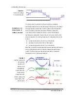
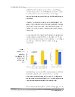
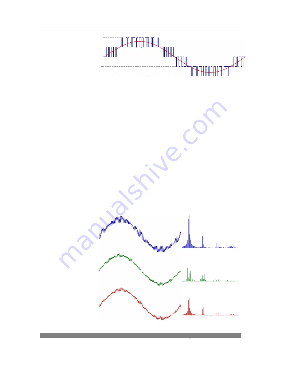
Some simulation results demonstrate the difference between the
conventional and the multilevel converter in terms of attenuation of
high-frequency components. Figure 8 shows the inverter current and its
harmonic spectrum (fs: switching frequency) for, respectively (from top to
bottom):
n
a conventional inverter with a 0.05 p.u. filter reactor;
n
a multilevel inverter with a 0.05 p.u. filter reactor;
n
a conventional inverter with a 0.10 p.u. filter reactor.
Note that, to match the current ripple and harmonic spectrum performance
seen in a three-level converter, a two-level topology requires a larger
reactor. Therefore, three-level based structures have a competitive
advantage in terms of size/weight reduction.
Inverter Current
Inverter Current
Inverter Current
1
x
fs 2
x
fs 3
x
fs 4
x
fs
1
x
fs 2
x
fs 3
x
fs 4
x
fs
1
x
fs 2
x
fs 3
x
fs 4
x
fs
Harmonic Spectrum
Harmonic Spectrum
Harmonic Spectrum
2- LEVEL INVERTER
REACTOR INDUCTANCE 0.05 p.u.
3- LEVEL INVERTER
REACTOR INDUCTANCE 0.05 p.u.
2- LEVEL INVERTER
REACTOR INDUCTANCE 0.10 p.u.
FIGURE 8
Inverter current and
its harmonic
spectrum for
various circuit
configurations:
2-level with a 5%
reactor (blue),
3-level with a 5%
reactor (green) and
2-level with a 10%
reactor (red).
Compactness is an
inherent feature of
multilevel converters.
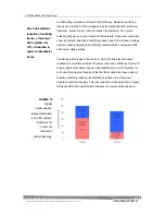
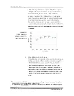
FIGURE 7
Line-to-line voltage
in a 3-level inverter
Содержание T90S3S08KS6XSN
Страница 21: ......
Страница 23: ......
Страница 25: ......
Страница 27: ......
Страница 29: ...G9000 Installation and Operation Manual ...
Страница 31: ...G9000 Installation and Operation Manual ...
Страница 98: ...G9000 Installation and Operation Manual 61 APPENDIX A Installation Planning Guides IPG ...
Страница 99: ...62 G9000 Installation and Operation Manual ...
Страница 100: ...G9000 Installation and Operation Manual 63 ...
Страница 101: ...64 G9000 Installation and Operation Manual ...
Страница 102: ......
Страница 104: ......
Страница 105: ......
Страница 106: ......
Страница 107: ......
Страница 108: ......
Страница 109: ......
Страница 110: ......
Страница 111: ......
Страница 112: ......
Страница 113: ......
Страница 114: ......
Страница 115: ......
Страница 116: ......
Страница 117: ......
Страница 118: ......
Страница 119: ......
Страница 120: ......
Страница 121: ......
Страница 122: ......
Страница 123: ......
Страница 124: ......
Страница 125: ......
Страница 126: ......
Страница 127: ......
Страница 128: ......
Страница 129: ......
Страница 130: ......
Страница 131: ......

