background image

– 8 –

EN

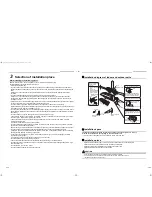
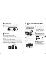
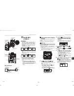
Heat insulator wrapping cross section A-A

Make the slit part of heat insulator to upward.

Insulating the pipes

Insulate the indoor unit completely so there are no 
gaps using the heat insulator provided.

CAUTION

Securely apply insulation all the way up to the pipe 
connecting section of the indoor unit so that there is no 
exposed area. (the pipe exposed to the outside causes 
water leak.)
When wrapping the heat insulator around pipes, make 
sure the slit aperture toward the ceiling surface.

CAUTION

• Bind the auxiliary pipes (two) and system 

interconnection wire and control wiring with facing 
tape tightly. In case of leftward piping and rear 
leftward piping, bind the auxiliary pipes (two) only with 
facing tape.

• Carefully arrange pipes so that any pipe does not stick 

out of the rear plate of the indoor unit.

• Carefully connect the auxiliary pipes and connecting 

pipes to one another and cut off the insulating tape 
wound on the connecting pipe to avoid double-taping 
at the joint, moreover, seal the joint with the vinyl tape, 
etc.

• Since dew results in a machine trouble, make sure to 

insulate both the connecting pipes.
(Use polyethylene foam as insulating material.)

• When bending a pipe, carefully do it, not to crush it.

7

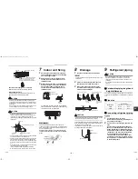
Indoor unit fixing

1

Pass the pipe through the hole in the wall, 
and hook the indoor unit on the installation 
plate at the upper hooks.

2

Swing the indoor unit to right and left to 
confirm that it is firmly hooked up on the 
installation plate.

3

While pressing the indoor unit onto the wall, 
hook it at the lower part on the installation 
plate. Pull the indoor unit toward you to 
confirm that it is firmly hooked up on the 
installation plate.

For detaching the indoor unit from the installation 
plate, pull the indoor unit toward you while pushing 
its bottom up at the specified parts.

REQUIREMENT

The lower part of indoor unit may float, due to the 
condition of piping and you cannot fix it to the installation 
plate. In that case, use the screws provided to fix the unit 
and the installation plate.

Especially when the pipes are pulled out from the 
left side, the unit must be screwed to the installation 
plate.

A

A

10

Heat insulator provided

Indoor unit shield pipe

Cut the heat insulator of the gas pipe 

(locally procured) leaving a 10 mm 

overlap with the shield of the shield pipe.

Liquid side

Gas side

System interconnection wire

Indoor unit

Auxiliary

pipes

Installation 

plate

Wired remote controller 

wiring

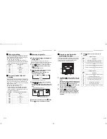
1

2

Press

(unhook)

Hook

Hook here

Installation plate

Push

Push

screw

screw

8

Drainage

1

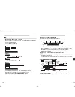
Run the drain hose sloped downwards.

NOTE

Hole should be made at a slight downward slant on the 
outdoor side.

2

Put water in the drain pan and make sure 
that the water is drained out of doors.

3

When connecting extension drain hose, 
insulate the connecting part of extension 
drain hose with shield pipe.

CAUTION

Arrange the drain pipe for proper drainage from the unit.
Improper drainage can result in dew-dropping.

This air conditioner has the structure designed to drain 
water collected from dew, which forms on the back of 
the indoor unit, to the drain pan.
Therefore, do not store the power cord and other parts 
at a height above the drain guide.

9

Refrigerant piping

CAUTION

When the refrigerant pipe is long, provide support 
brackets at intervals of 2.5 m to 3 m to clamp the 
refrigerant pipe. Otherwise, abnormal sound may be 
generated.
Use the flare nut attached with the indoor unit or R410A 
flare nut.

„

Permissible piping length and 
height difference

They vary depending on the outdoor unit. For details, 
refer to the Installation Manual attached to the outdoor 
unit.

„

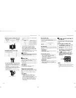
Pipe size

„

Connecting refrigerant piping

Flaring

1

Cut the pipe with a pipe cutter. 
Remove burrs completely. (remaining burrs 
may cause gas leakage.)

2

Insert a flare nut into the pipe, and flare the 
pipe.
Use the flare nut provided with the unit or 
the one used for the R410A refrigerant. The 
flaring dimensions for R410A are different 
from the ones used for the conventional R22 
refrigerant. A new flare tool manufactured 
for use with the R410A refrigerant is 
recommended, but the conventional tool 
can still be used if the projection margin of 
the copper pipe is adjusted to be as shown 
in the following table.

Do not put the 
drain hose end 
in the drainage 
ditch.

Do not put the 
drain hose end 
into water.

Do not rise the drain hose.

Do not form the drain hose 
into a wavy shape.

50 mm 
or more

Drain hose

Inside the 
room

Shield pipe

Extension drain hose

Wall

Drain guide

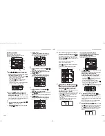
Space for pipes

Model: RAV-

Pipe size (mm)

Gas side

Liquid side

SM56

Ø12.7

Ø6.4

SM80

Ø15.9

Ø9.5

15-EN

16-EN

+001111055801_01EN.book  Page 8  Monday, September 5, 2011  11:12 AM

Содержание RAV-SM566KRT-E

Страница 1: ...xxxxxxxxxxxxxxxx xx Xxxxxxx xxxxxxxxxxxxxxxxxxxxxxxx xx Xxxxxxx xxxxxxxxxxxxxxxxxxxxxxxx xx Xxxxxxx xxxxxxxxxxxxxxxxxxxxxxxx xx Xxxxxxx xxxxxxxxxxxxxxxxxxxxxxxx xx Xxxxxxx AIR CONDITIONER SPLIT TYPE Indoor Unit Model name High Wall Type RAV SM566KRT E RAV SM806KRT E Installation Manual For commercial use 001111055801_01EN book Page 1 Monday September 5 2011 11 12 AM ...

Страница 2: ...llation relocation and removal has the qualifications pertaining to this refrigerant handling and piping work as stipulated by the local laws and regulations and he or she is a person who has been trained in matters relating to refrigerant handling and piping work on the air conditioners made by Toshiba Carrier Corporation or alternatively he or she has been instructed in such matters by an indivi...

Страница 3: ...tection for electricians and from heat Warning indications on the air conditioner unit Warning indication Description WARNING ELECTRICAL SHOCK HAZARD Disconnect all remote electric power supplies before servicing WARNING Moving parts Do not operate unit with grille removed Stop the unit before the servicing CAUTION High temperature parts You might get burned when removing this panel CAUTION Do not...

Страница 4: ...t the possibility of high winds and earthquake If the air conditioner is not installed appropriately a unit may topple over or fall down causing an accident If refrigerant gas has leaked during the installation work ventilate the room immediately If the leaked refrigerant gas comes in contact with fire noxious gas may generate Refrigerant piping Install the refrigerant pipe securely during the ins...

Страница 5: ...ompanied with the new refrigerant refrigerating oil has also been changed Therefore during installation work be sure that water dust former refrigerant or refrigerating oil does not enter the refrigerating cycle To prevent charging an incorrect refrigerant and refrigerating oil the sizes of connecting sections of charging port of the main unit and installation tools are changed from those for the ...

Страница 6: ...unit installed that would be compromised by wetness If the drain has become blocked or when the humidity is over 80 condensation from the indoor unit will drip possibly causing damage to anything underneath In the case of the wireless type of system rooms with the inverter type of fluorescent lighting or locations exposed to direct sunlight The signals from the wireless remote controller may not b...

Страница 7: ...cooled well Screen OK NO GOOD 5 Cutting a hole and mounting installation plate Cutting a hole In case of installing the refrigerant pipes from the rear 1 Decide the hole position for piping at 180 mm from the arrow mark Ö on the installation plate and drill a hole at a slight downward slant toward outdoor side Pipe hole dia 65 mm SM56 type Pipe hole dia 80 mm SM80 type NOTE When drilling a wall th...

Страница 8: ...e drain cap by needle nose pliers and pull out How to fix the drains cap 1 Insert hexagonal wrench dia 4 mm in a centre head 2 Firmly insert drains cap CAUTION Firmly insert the drain hose and drain cap otherwise water may leak How to remove the drain hose 1 Remove the front panel 2 Remove the screws of drain hose 3 Pull out the drain hose How to fix the drain hose 1 Put the drain hose 2 Screw the...

Страница 9: ... of the gas pipe locally procured leaving a 10 mm overlap with the shield of the shield pipe Liquid side Gas side System interconnection wire Indoor unit Auxiliary pipes Installation plate Wired remote controller wiring 1 2 Press unhook Hook Hook here Installation plate Push Push screw screw 8 Drainage 1 Run the drain hose sloped downwards NOTE Hole should be made at a slight downward slant on the...

Страница 10: ...nventional tool used 6 4 9 5 0 to 0 5 1 0 to 1 5 12 7 15 9 Outer dia of copper pipe A 0 0 4 6 4 9 1 9 5 13 2 12 7 16 6 15 9 19 7 B A Work using double spanner Outer dia of connecting pipe mm Tightening torque N m 6 4 14 to 18 1 4 to 1 8 kgf m 9 5 33 to 42 3 3 to 4 2 kgf m 12 7 50 to 62 5 0 to 6 2 kgf m 15 9 63 to 77 6 3 to 7 7 kgf m Open the valve fully Open the valve of the outdoor unit fully A h...

Страница 11: ...emote controllers Up to 300 m 2 remote controllers including a wireless remote controller Up to 400 m Total wire length of remote controller inter unit wiring L1 L2 Ln Up to 200 m A B L1 L L2 Ln Indoor unit Remote controller inter unit wiring Indoor unit Indoor unit Indoor unit Remote controller max 8 units Remote controller wiring Wiring between indoor unit and outdoor unit 1 Figure below shows t...

Страница 12: ...y System interconnection wire 3 is not used 3 Connect the earth wire to the earth screw located on the underside of the electrical control box 4 Clamp the system interconnection wire with the cord clamp 5 Attach the terminal cover and the air intake grille to the indoor unit When using optional wired remote controller The system interconnection wire and the wired remote controller wire can be conn...

Страница 13: ...e air conditioner before making settings CAUTION Set only the CODE No shown in the following table Do NOT set any other CODE No If a CODE No not listed is set it may not be possible to operate the air conditioner or other trouble with the product may result 1 Push button and TEMP button simultaneously for 4 seconds or more After a while the display flashes as shown in the figure Confirm that the C...

Страница 14: ...tting SET DATA Filter sign term 0000 None 0001 150 H factory default 0002 2500 H 0003 5000 H 0004 10000 H SET DATA Detection temperature shift value 0000 No shift 0001 1 C 0002 2 C factory default 0003 3 C 0004 4 C 0005 5 C 0006 6 C UNIT No 1 1 UNIT No 1 2 UNIT No 1 3 UNIT No 1 4 Setting of power level in power saving mode Remote controller switch monitoring function This function is available to ...

Страница 15: ...ire of the remote controller When the power supply has been turned on the automatic address setup starts and which indicates that address is being set up flashes on the display part in about 3 minutes During setup of automatic address the remote controller operation is not accepted Required time up to the finish of automatic addressing is approx 5 minutes NOTE In some cases it is necessary to chan...

Страница 16: ...k the changed contents Address change check Before change 3 3 1 After change 2 2 2 Pushing button clears the contents of which setup was changed In this case procedure from 2 is repeated 7 After check of the changed contents push button setup is determined When button is pushed the display disappears and the status becomes the usual stop status when button is pushed the operation from the remote c...

Страница 17: ...ptional wired remote controller Connect the central control wire to the terminals and on the terminal block in the same way as the optional wired remote controller For details refer to the installation manual of the applicable central control system SET DATA 8 C Operation setting 0000 None factory default 0001 8 C Operation setting Display changes according to the model No of indoor unit 3 4 3 4 2...

Страница 18: ... C302 DB301 L301 SW01 T301 L41 L201 CN213 CN104 IC01 SW02 BZ01 CN101 CN102 MCC 1510 ON 1 2 ON 1 2 Factory default After setting SW01 OFF SW02 OFF SW01 ON SW02 OFF Centrally control the system by connecting to the TCC LINK central control system Setting central control addresses When air conditioners of the SDI DI series are connected to the TCC LINK central control system for central control using...

Страница 19: ...change For 30 or more refrigeration systems when they are used together with the SMMS series the number of refrigeration systems of the SMMS series is included The line address change setting procedure for up to the 29th refrigeration system is the same as that described in step 1 on the previous page Since all line addresses are set to 1 except for group control by the automatic address setup fun...

Страница 20: ...re 1 5 Push check button to cancel release from the test run mode TEST disappears on the display and the status returns to a normal 2 4 3 1 5 When a test run is not performed properly When a test run is not performed properly refer to the error code and the part to be checked on Troubleshooting In case of wireless remote controller Forced test operation is performed in a different way REQUIREMENT ...

Страница 21: ...nce can extend the life of the product though it involves the owner s expense Failure to clean the indoor and outdoor units regularly will result in poor performance freezing water leakage and even compressor failure Inspection before maintenance Following inspection must be carried out by a qualified installer or qualified service person Maintenance list Parts Inspection method Heat exchanger Acc...

Страница 22: ...oor P C board No data is received from the remote controller or network adapter Auto reset E04 Indoor unit outdoor unit serial communication error Indoor System interconnection wires indoor P C board outdoor P C board Serial communication error between indoor unit and outdoor unit Auto reset IPDU CDB communication error E08 Duplicated indoor addresses Indoor Indoor address setting error The same a...

Страница 23: ...peration continued thermostat OFF P01 ALT Indoor unit fan error Indoor Indoor fan motor indoor P C board Indoor AC fan error fan motor thermal relay activated was detected Entire stop Wired remote controller display Wireless remote controller Sensor block display of receiving unit Main defective parts Judging device Parts to be checked error description Airconditioner status Indication OperationTi...

Страница 24: ...1111055801 001111055801_01EN book Page 65 Monday September 5 2011 11 12 AM ...

Отзывы: