– 16 –
EN
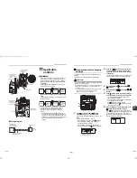
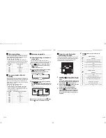
8 °C operation (SDI series4
and DI series4 only)
Pre-heating operation can be set for cold regions
where room temperature drops to below zero.
1
Push
+
+
buttons simultaneously
for 4 seconds or more when the air
conditioner is not working.
After a while, the display part flashes as
shown below. Check the Displayed CODE
No. is [10].
When the CODE No. is other than [
10
], push
button to erase the display and repeat procedure
from the first step.
(After pushing
button, operation of the remote
controller is not accepted for approx. 1 minute.)
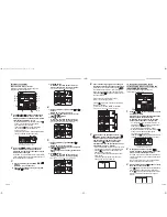
2
Every time
button is pushed, the
indoor unit No. in the group control is
displayed in order. Select the indoor unit of
which setup is changed. In this time, the
position of the indoor unit of which setup is
changed can be confirmed because fan of
the selected indoor unit operate.
3
Specify CODE No. [d1] TEMP.
/
buttons.
4
Select SET DATA [0001] TIME
/
buttons.
5
Push
button.
In this time, the setup finishes when the display
changes from flashing to lighting.
6
Push
button. (setup is determined.)
When
button is pushed, the display
disappears and the status becomes the usual stop
status. (when
button is pushed the operation
from the remote controller is not accepted for
approx. 1 minute.)
Central control system
Air conditioners at multiple locations can be controlled
individually for each refrigeration system from a control
room.
Central control is not available with the supplied
wireless remote controller. Use the optional wired
remote controller.
▼
Wiring for central control
The terminal block for central control wiring (
and
) is the same as that for optional wired remote
controller. Connect the central control wire to the
terminals (
and
) on the terminal block in the
same way as the optional wired remote controller.
For details, refer to the installation manual of the
applicable central control system.
SET DATA
8 °C Operation setting
0000
None
(factory default)
0001
8 °C Operation setting
(* Display changes according to
the model No. of indoor unit.)
3
4
3
4
2
3
1
U
3
U
4
A
B
Terminal block
for wired
remote
controller /
central control
wiring
Cord clamp
Wired
remote
controller
wire
Central
control wire
▼
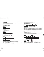
Centrally control the system by the SDI, DI series on their own setting for the terminating resistor
is required.
• Use switch SW01 for the setting.
• Make the terminating resistor setting only for the indoor unit with the smallest line address number.
1 2 3
A B
U3 U4
U1
U3
U2
U4
A B
U3 U4
A B
U1
U3
U2
U4
1 2 3
1 2 3
1 2 3
1 2 3
A B
U3 U4
1 2 3
1 2 3
A B
1 2 3
1 2 3
A B
1 2 3
Central
control
device
Central
control
device
Central control device: Up to 10 units
Refrigeration
system 1
Refrigeration
system 2
Refrigeration
system 3
Header
indoor
unit
Indoor
unit
TCC-LINK
adapter
(option)
Required for
indoor units
other than
high wall type
Remote
controller
wiring
Remote controller
Remote controller
Remote controller
Group operation (up to 8 units)
(OFF at factory default)
Line address
SW01 bit1
Remarks
1
ON
Set bit1 of
SW01 to ON
2
OFF
Factory default
Outdoor
unit
Refrigeration
system 4
Remote controller
Follower
indoor unit
Header
indoor unit
Follower
indoor unit
Follower
indoor unit
System interconnection wire
(AC 220-240 V serial)
Central control wires
*Connect 1 and 2 only
Twin and triple system (example of triple system)
4
OFF
Factory default
31-EN
32-EN
+001111055801_01EN.book Page 16 Monday, September 5, 2011 11:12 AM

