– 11 –
Wiring connection
(single system)
REQUIREMENT
• Be sure to connect the wires matching the terminal
numbers.
Incorrect connection causes a trouble.
• Keep a margin (approx. 100 mm) on a wire to hang
down the electrical control box at servicing, etc.
• The low-voltage circuit is provided for the wired
remote controller.
(Do not connect the high-voltage circuit)
▼
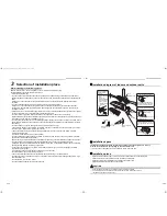
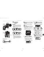
When using the supplied wireless remote
controller
The system interconnection wire can be connected
without removing the front panel.
1
Remove the air intake grille.
Open the air intake grille upward and pull it toward
you.
2
Remove the terminal cover.
3
Insert the system interconnection wire
(according to the local rule) into the pipe
hole on the wall.
4
Take the system interconnection wire out of
the cable slot on the rear panel so that it
protrudes about 150 mm from the front.
5
Insert the system interconnection wire fully
into the terminal block and secure it tightly
with screws.
Tightening torque: 1.2 N
·
m (0.12 kgf
·
m)
Secure the earth wire with the earth screw.
6
Clamp the system interconnection wire with
the cord clamp.
7
Attach the terminal cover and the air intake
grille to the indoor unit.
CAUTION
• Be sure to refer to the wiring diagram attached inside
the front panel.
• Check local electrical cords and also any specific
wiring instructions and limitations.
1
2
3
1
2
3
Terminal block for
Indoor / Outdoor
connecting
Clamp base
Earth screw
Screw
Screw
Screw
Cord
clamp
Terminal cover
3
2
1
L
N
150
40
30
60
Earth wire
System
interconnection
wire
about
150 mm
<Stripping length of the system interconnection wire>
Unit : mm
1
2
3
<Single system connection>
Terminal block for
Indoor / Outdoor
connecting wiring
Cord clamp
Earth screw
System
interconnection wire
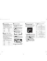
Wiring connection (twin,
triple, double twin system)
1
Connect a header unit by following the
procedure of wiring connection for single
system.
2
Connect system interconnection wire 1 and
2 of follower unit to terminal 1 and 2 on
terminal block respectively.
System interconnection wire 3 is not used.
3
Connect the earth wire to the earth screw
located on the underside of the electrical
control box.
4
Clamp the system interconnection wire with
the cord clamp.
5
Attach the terminal cover and the air intake
grille to the indoor unit.
▼
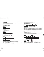
When using optional wired remote controller
The system interconnection wire and the wired remote
controller wire can be connected without removing the
front panel.
1
Remove the air intake grille.
Open the air intake grille upward and pull it toward
you.
2
Remove the terminal cover and the clamp
base.
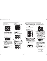
3
Insert the system interconnection wire and
wired remote controller wire (according to
the local rule) into the pipe hole on the wall.
4
Take the system interconnection wire and
wired remote controller wire out of the cable
slot on the rear panel so that it protrudes
about 150 mm from the front.
5
Insert the wired remote controller wire fully
into the wired remote controller / central
control terminal block,
, ,
and secure it
tightly with screws.
• Strip off approx. 9 mm the wire to be connected.
• Non polarity, 2 core wire is used for wiring of the
wired remote controller. (0.5 mm
2
to 2.0 mm
2
wires)
6
Clamp the wired remote controller wire with
the cord clamp.
7
Install the clamp base with a screw.
8
Insert the system interconnection wire fully
into the terminal block and secure it tightly
with screws.
Tightening torque: 1.2 N
·
m (0.12 kgf
·
m)
Secure the earth wire with the earth screw.
9
Clamp the system interconnection wire with
the cord clamp.
10
Attach the terminal cover and the air intake
grille to the indoor unit.
CAUTION
• Be sure to refer to the wiring diagram attached inside
the front panel.
• Check local electrical cords and also any specific
wiring instructions and limitations.
• Do not catch the wired remote controller wire when
installing the clamp base.
2
1
90
70
Earth wire
<Stripping length of the system interconnection wire>
Unit : mm
Follower unit side
1
2
3
<Twin, triple, double twin system connection>
Header unit system
interconnection wire
Earth screw
Follower unit system
interconnection wire
Cord clamp
A
B
21-EN
22-EN
+001111055801_01EN.book Page 11 Monday, September 5, 2011 11:12 AM


