– 116 –
No. Part name
Procedure
Remarks
i
Compressor
and
compressor
lead
1. Removing a broken compressor
1) Recover refrigerant gas.
2) Following to work of item 1 and
f
of
c
.
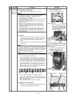
3) Remove the piping panel (front).
Remove the screws from piping panel (front) and base
plate. (2 pcs, Ø4 × 10 hexagon screws)
Remove the screws from the piping panel (front) and
piping panel (rear). (1 pcs, Ø4 × 10 hexagon screw)
4) Remove the piping panel (rear). Remove the screws on
the piping panel (rear) and the bottom plate.
(2 pcs, Ø4×10 hexagon screws)
5) Remove the soundproofing material (upper, inner, and
outer).
6) Remove the compressor’s terminal cover and
compressor lead and compressor case thermostat.
7) Remove the TD sensor fixed to the discharge pipe.
8) Following to work of item t 2) of 1 of
g
.
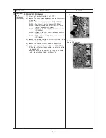
9) Remove the fixing the screws compressor lead from
the comp substrate. (3 screws)
10) Remove the fixing the screws ferrite core and
compressor lead. (1 pcs, ST3T Ø4 × 8)
11) Remove the discharge and suction pipes connected
to the compressor using a burner.
WARNING
Ensure extreme caution when removing piping by melting
the weld with a burner as fire may result if there is any oil
within the piping.
NOTE
Carefully avoid contact with the 4-way valve and PMV with
the flame (could result in a malfunction).
12) Remove the refrigeration cycle discharge and suction
pipes by pulling them upwards.
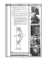
13) Remove the compressor nuts securing the
compressor to the base plate. (3 nuts)
14) Pull the compressor forwards.
NOTE
The compressor weighs at least 20kg. Ensure two people
carry out the work.
Pipe panel (front)
Pipe panel (rear)
TD sensor
Code clamp
(heat resistant)
Pipe cover
Pipe cover
Pipe cover
Compressor lead
Case thermostat
lead
Fixing the screw compressor lead
(3 screws)
Ferrite core
Fixing the screw ferrite core
(1 screw)
Compressor nuts
Remove the screws

