– 115 –
No. Part name
Procedure
Remarks
h
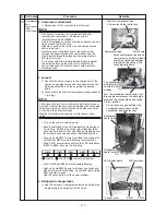
Fan motor
1) Following to work of item 1,
d
and
e
of
c
.
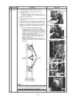
2) Remove the flange nut from the fan motor and
propeller fan.
• Loosen the flange nut by turning clock wise.
(To tighten the flange nut, turn it counter clockwise)
3) Remove the propeller fan.
4) Remove the fan motor connector from the FAN-IPDU
P.C. board.
5) Remove the fan motor lead from the fan motor lead
fixing rubber where it penetrates the separate plate.
6) Remove the screws (4 each) fixing it in place while
supporting it by hand so that the fan motor does not
fall.
∗
Precautions when assembling the fan motor
• Tighten the flange nut to 4.95 N•m (50 kgf·cm).
• To prevent the fan motor leads from coming in
contact with the propeller fan ensure to adjust the
length of the fan motor lead fixing rubber so that
the fan motor lead has no slack.
Attach the fan motor lead fixing rubber to the
separate plate so that the projection is on the
refrigeration cycle side.
• Ensure to bundle again with a commercially
available code clamp where the code clamp was
removed.
Propeller fan
Propeller fan
Loosen by turning
Loosen by turning
clockwise
clockwise
Flange nut
Fan motor
Fan motor
Fan motor
Fan motor
Upper fan motor connector
Upper fan motor connector
Lower fan motor connector
Lower fan motor connector
Fan motor lead fixing rubber
Fan motor lead fixing rubber
Sheet metal band
Sheet metal band
Protrusion/refrigeration
Protrusion/refrigeration
cycle side
cycle side
Loosen by turning
clockwise
Fan motor
Fan motor
Upper fan motor connector
Lower fan motor connector
Fan motor lead fixing rubber
Sheet metal band
Protrusion/refrigeration
cycle side
Metal band
Sheet metal
Sheet metal
band
band
Sheet metal
band
NOTE
Ensure to fix the fan motor lead to the motor base with the
motor base metal band and sheet metal band to ensure it
does not come in contact with the propeller fan.


