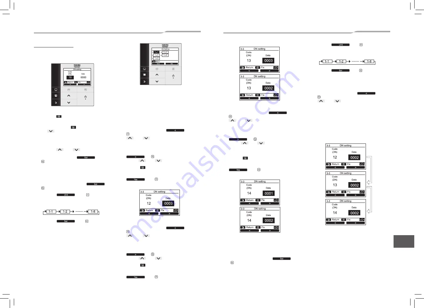
[Procedure example]
Manual address setup procedure
While the operation stops, change the setup.
(Stop the operation of the unit.)
1
Push the [
MENU] button to display the
menu screen.
Push and hold the [
MENU] button and
the [
˅ ] button at the same time to
display the “Field setting menu”.
Push and hold the buttons for more than 4
seconds.
Push the [
˄ ] / [
˅ ] button to select
“DN setting” on the “Field setting menu”
screen, then push the “
Set”
[ F2] button.
The fan and louver of the indoor unit operate.
When the group control is used, the fan and
louver of the selected indoor unit operate.
Select the group-controlled function on the
menu screen, then push the “
Set”
[ F2] button.
Push the “
unit” [ F1] button to
select the unit to set.
The selected unit changes as follows each
time the button is pushed:
Push the “
Set” [ F2] button.
The setting display for the selected unit
appears.
(For a group control, No. of the firstly displayed
indoor unit becomes the header unit.)
2
The indoor UNIT No. in the group control is
displayed in order. Select the indoor unit of
which setup is changed.
In this time, the position of the indoor unit of
which setup is changed can be confirmed
because fan of the selected indoor unit operate.
3
1. Specify CODE No. [
12
] with Move the cursor to
select “Code(DN)” with the “
<”
[
F1] button, then set “Code(DN)” with the
[
˄
] / [
˅
] button.
(CODE No. [
12
]: Line address)
2. Change the line address from [
3
] to [
2
] with
Move the cursor to select “Data” with the
“
>” [
F2] button, then set “Data”
with the [
˄
] / [
˅
] button.
3. Push the [
MENU] button to set the other
Code (DN) and Data. After “Continue?” is
displayed on the screen, push the
“
Yes” [
F1] button.
5
1. Specify CODE No. [
14
] with Move the cursor to
select “Code(DN)” with the “
<”
[
F1] button, then set “Code(DN)” with the
[
˄
] / [
˅
] button.
(CODE No. [
14
]: Group address)
2. Change the SET DATA from [
0001
] to [
0002
] with
Move the cursor to select “Data” with the
“
>” [
F2] button, then set “Data”
with the [
˄
] / [
˅
] button.
(SET DATA [Header unit:
0001
] [Follower unit:
0002
])
3. Push the [
MENU] button to set the other
Code (DN) and Data. After “Continue?” is
displayed on the screen, push the
“
Yes” [
F1] button.
6
If there is other indoor unit to be changed,
repeat procedure
2
to
5
to change the
setup.
When the above setup has finished, push
Select the group-controlled function on the
menu screen, then push the “
Set”
[ F2] button.
Push the “
unit” [ F1] button to
select the unit to set.
The selected unit changes as follows each
time the button is pushed:
Push the “
Set” [ F2] button.
The setting display for the selected unit
appears.
before change of setup, specify CODE No. [
12
],
[
13
], [
14
] in order with Move the cursor to
select “Code(DN)” with the “
<”
[
F1] button, then set “Code(DN)” with the
[
˄
] / [
˅
] button. and then check the
changed contents.
Address change check Before change:
[
3-3-1
] → After change: [
2-2-2
]
The contents of which
setup was changed.
(In this case, procedure from
2
is repeated.)
4
1. Specify CODE No. [
13
] with Move the cursor to
select “Code(DN)” with the “
<”
[
F1] button, then set “Code(DN)” with the
[
˄
] / [
˅
] button.
(CODE No. [
13
]: Indoor address)
2. Change the Indoor address from [
3
] to [
2
] with
Move the cursor to select “Data” with the
“
>” [
F2] button, then set “Data”
with the [
˄
] / [
˅
] button.
3. Push the [
MENU] button to set the other
Code (DN) and Data. After “Continue?” is
displayed on the screen, push the
“
Yes” [
F1] button.
(* Display changes according to
the model No. of indoor unit.)
Indoor UNIT No. before setup change is displayed.
Indoor UNIT No. before setup change is displayed.
Indoor UNIT No. before setup change is displayed.
Indoor UNIT No. before setup change is displayed.
� 22 �
43-EN
44-EN
EN
1115350171_EN,FR,ES.indd 23
19/3/2565 9:38:33


