– 54 –
FILE NO. SVM-
16041
Target outdoor unit (SMMS-i – Series 4)
CODE No.
Data
Format
Unit
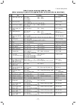
Remote controller display example
00
01
02
03
04
05
06
08
Indoor unit
data *2
System unit
data
Individual
data 1 of
outdoor
unit *3
CODE No.
Data
Format
Unit
Remote controller display example
U1 U2 U3 U4
Room temperature (in control)
Room temperature (Remote controller)
Air Temperature (TA)
Coil Temperature (TCJ)
Coil Temperature (TC2)
Coil Temperature (TC1)
Discharge temperature (TF) *1
PMV
˚C
˚C
˚C
˚C
˚C
˚C
˚C
pls
[0024]=24 ˚C
[0150]=1500 pls
09
Air Suction Temperature of direct expansion
coil (TSA) *1
[0024]=24
˚
C
[0048]=48
[0415]=41.5HP
[0004]=4
[0420]=42HP
FA
0A
0B
0C
0D
Outdoor Air Temperature (TOA) *1
Number of connected indoor units
Total horse power of connected indoor units
Number of connected outdoor units
Total horse power of outdoor units
˚C
—
HP
—
HP
15
16
17
18
19
1A
1B
1C
1D
1E
1F
25
26
27
28
29
2A
2B
2C
2D
2E
2F
35
36
37
38
39
3A
3B
3C
3D
3E
3F
45
46
—
48
49
4A
—
4C
4D
—
4F
Suction Temperature (TS)
Coil Temperature 1 (TE1)
Coil Temperature 2 (TE2)
Liquid Temperature (TL)
Outdoor Temperature (TO)
PMV1 + 2
PMV4
Current of compressor 1 (I1)
Current of compressor 2 (I2)
Current of compressor 3 (I3)
Outdoor fan current (IFan)
˚C
˚C
˚C
˚C
˚C
pls
pls
A
A
A
A
10 20 30 40
Detection pressure of high-pressure sensor
(Pd)
Detection pressure of low-pressure sensor
(Ps)
MPa
11 21 31 41
MPa
[0123]=1.23 MPa
12 22 32 42
Discharge temperature of compressor 1
(Td1)
Discharge temperature of compressor 2
(Td2)
14 24 34 —
Discharge temperature of compressor 3
(Td3)
13 23 33 43
[0024]=24 ˚C
[0050]=500 pls
[0135]=13.5 A
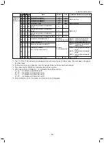
*1 The TF/TSA/TOA sensors are equipped only with some types of indoor units. The data does not appear for
other types.
*2 In the case of group connection, only the header indoor unit data can be displayed.
*3 The upper digit of CODE No. indicates the outdoor unit No.
*4 [(The upper digit of CODE No.) – 4] indicates the outdoor unit No.
1
∗
, 5
∗
... U1 outdoor unit (Header unit)
2
∗
, 6
∗
... U2 outdoor unit (follower unit 1)
3
∗
, 7
∗
... U3 outdoor unit (follower unit 2)
4
∗
, 8
∗
... U4 outdoor unit (follower unit 3)
*5 Only CODE No. 5• of U1 outdoor unit (Header unit) is displayed.
x1
x1
x1
x1
x1
x1
x1
x1
x1
x1
x1
x1/10
x10
x10
x100
x100
x1
x1
x1
x1
x1
x1
x1
x1
x1
x1
x10
x10
x10
x10
˚C
˚C
˚C
˚C
Содержание MMU-AP0094HP1-E
Страница 19: ... 19 FILE NO SVM 16041 2 WIRING DIAGRAM ...


