– 47 –
FILE NO. SVM-
16041
�
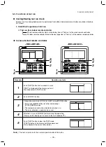
Confirmation of indoor unit No. position
1. To know the indoor unit addresses though position of the indoor unit is recognized
• In case of individual operation (Wired remote controller : indoor unit = 1 : 1)
(Follow to the procedure during operation)
1 2
END
Operation
<Operation procedure>
2
1
SET
TIME
TIMER SET
TEST
FILTER
RESET
TEMP.
CL
FAN
SAVE
SWING/FIX
VENT
MODE
ON / OFF
UNIT LOUVER
1 2 3
END
<Operation procedure>
3
1
2
SET
TIME
TIMER SET
TEST
FILTER
RESET
TEMP.
CL
FAN
SAVE
SWING/FIX
VENT
MODE
ON / OFF
UNIT LOUVER
<Procedure>
1
Push
ON / OFF
button if the unit stops.
2
Push
UNIT LOUVER
(left side button) button.
Unit No. 1-1 is displayed on LCD.
(It disappears after several seconds.)
The displayed unit No. indicate line address and
indoor unit address.
(When other indoor units are connected to the
identical remote controller (Group control unit),
other unit numbers are also displayed every
pushing
UNIT LOUVER
(left side button) button.
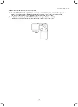
2. To know the position of indoor unit by address
• To confirm the unit No. in the group control
(Follow to the procedure during operation) (in this procedure, the indoor units in group control stop.)
<Procedure>
The indoor unit numbers in the group control are
successively displayed, and fan, louver, and drain pump
of the corresponding indoor unit are turned on.
(Follow to the procedure during operation)
1
Push
VENT
and
TEST
buttons simultaneously for
4 seconds or more.
• Unit No.
is displayed.
• Fans and louvers of all the indoor units in the
group control operate.
2
Every pushing
UNIT LOUVER
(left side button) button,
• The unit No. displayed at the first time indicates
the header unit address.
• Fan and louver of the selected indoor unit only
operate.
3
Push
TEST
button to finish the procedure.
All the indoor units in the group control stop.
successively displayed.
the unit numbers in the group control are
�
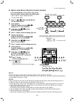
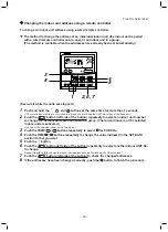
Address setup (Manual setting from remote controller)
In case that addresses of the indoor units will be
determined prior to piping work after cabling work
• Set an indoor unit per a remote controller.
• Turn on power supply.
1
Push
SET
+
CL
+
TEST
buttons simultaneously
for 4 seconds or more.
2
(Line address)
Using the temperature setup
/
buttons, set
��
to the CODE No.
3
Using timer time
/
buttons,
set the line address.
4
Push
SET
button. (OK when display goes on.)
5
(Indoor unit address)
Using the temperature setup
/
buttons, set
��
to the CODE No.
6
Using timer time
/
buttons,
set 1 to the line address.
7
Push
SET
button. (OK when display goes on.)
8
(Group address)
Using the temperature setup
/
buttons, set
��
to the CODE No.
9
Using timer time
/
buttons,
set
����
to Individual,
����
to
Master unit and
����
to sub unit.
10
Push
SET
button.
(OK when display goes on.)
11
Push
TEST
button.
Setup completes.
(The status returns to the usual stop status.)
(Example of 2-lines cabling)
(Real line: Cabling, Broken line: Refrigerant pipe)
For the above example, perform setting by connecting singly the
wired remote controller without remote controller inter-unit cable.
Group address
Individual
: 0000
In case of group control
Outdoor
Outdoor
Indoor
Indoor
Indoor
Indoor
Indoor
unit
Line address 1
Indoor unit address 1
Group address 1
1
2
2
1
3
2
2
1
2
2
2
2
<Operation procedure>
1 2 3 4 5 6
1
3, 6, 9
END
11
2, 5, 8
4, 7, 10
SET
TIME
TIMER SET
TEST
FILTER
RESET
TEMP.
CL
FAN
SAVE
SWING/FIX
VENT
MODE
ON / OFF
UNIT LOUVER
7 8 9 10 11
END
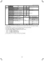
Note 1)
When setting the line address from the remote controller, do not use Address 29 and 30.
As they are addresses which cannot be set to the outdoor unit, if they are set, the check code [E04] (Indoor/Outdoor
communication circuit error) is issued.
Note 2)
When an address was manually set from the remote controller and the central control over the refrigerant lines is
carried out, perform the following setting for the Master unit of each line.
• Set the line address for every line using SW13 and 14 on the interface P.C. board of the center unit in each line.
• Except the least line address No., turn off SW30-2 on the interface P.C. board of the Master units in the lines
connected to the identical central control.
(Draw the terminal resistances of indoor/outdoor and central control line wirings together.)
• For each refrigerant line, connect the relay connector between Master unit [U1U2] and [U3U4] terminals.
• After then set the central control address.
(For setting of the central control address, refer to the Installation manual for the central control equipment.)
Follower
Header unit
Header unit : 0001
Follower unit : 0002
Содержание MMU-AP0094HP1-E
Страница 19: ... 19 FILE NO SVM 16041 2 WIRING DIAGRAM ...


