– 96 –
FILE NO. SVM-
16041
No.
8
Part name
Drain pump
Procedure
1. Detachment
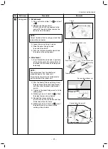
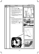
1) Carry out works of item 1 of 2 and item
1 of 6 .
2) Remove the drain pump connector (CN504,
White, 2P) connected to the control P.C.
board and then remove the lead wire from
the clamp.
3) Remove the fixing screws and then remove
the drain pump. (Ø4 × 10, 3 pcs.)
4) As shown in the right figure, first pull out
the connecting part of the drain pump and
the drain hose from the drain port and then
take out the drain pump.
5) Set direction of the knob of the hose band
downward, slide it from the pump connect-
ing part to the hose side and then remove
the drain hose from the drain pump.
6) Pass the connector of the drain pump lead
wire through the wiring taking-out port and
then take out the drain pump.
2. Attachment
1) Enter your hand into the drain port and
pass the connector of the drain pump lead
wire through the wiring taking-out port.
2) Connect the drain hose to the drain pump
as before.
NOTE :
Insert the drain hose up to the end of the
drain pump connecting part, apply band to
the white mark position of the hose and then
set the band knob upward.
3) Return the drain pump to the indoor unit
and then mount it as before using the fixing
screws. (Ø4 × 10, 3 pcs.)
4) Connect the drain pump connector (CN504,
White, 2P) to the control P.C. board and
then fix it as before with the clamp.
5) Following to words of item 2 of 6 and item
2 of 2 , mount the drain cap, the electric
parts box cover and the suction grille as
before.
Remarks
Fixing screw A
Drain port
Drain pump
CN504
Drain pump
lead wire
Wiring taking-out port
Clamp
Drain hose
Drain pump
Pump connecting part
Slide to drain hose side.
Hose band
Drain port
Drain pump
lead wire
Pump connecting part
Slide to drain hose side.
Hose band
Содержание MMU-AP0094HP1-E
Страница 19: ... 19 FILE NO SVM 16041 2 WIRING DIAGRAM ...


