background image

– 23 –

45-EN

46-EN

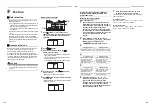
F01

ALT

Indoor unit TCJ sensor trouble

Indoor unit

F02

ALT

Indoor unit TC2 sensor trouble

Indoor unit

F03

ALT

Indoor unit TC1 sensor trouble

Indoor unit

F04

F04

ALT

TD1 sensor trouble

I/F

F05

F05

ALT

TD2 sensor trouble

I/F

F06

F06

01: TE1 sensor
02: TE2 sensor

ALT

TE1 sensor trouble
TE2 sensor trouble

I/F

F07

F07

01: TL1 sensor
02: TL2 sensor
03: TL3 sensor

ALT

TL1,TL2 or TL3 sensor trouble

I/F

F08

F08

ALT

TO sensor trouble

I/F

F10

ALT

Indoor unit TA sensor trouble

Indoor unit

F12

F12

01: TS1 sensor
03: TS3 sensor

ALT

TS1 or TS3 sensor trouble

I/F

F13

F13

01: Comp. 1 side
02: Comp. 2 side

ALT

TH sensor trouble

IPDU

F15

F15

ALT

Outdoor unit temp. sensor miswiring (

ТЕ

, TL)

I/F

F16

F16

ALT

Outdoor unit pressure sensor miswiring (Pd, Ps)

I/F

F23

F23

ALT

Ps sensor trouble

I/F

F24

F24

ALT

Pd sensor trouble

I/F

F29

SIM

Indoor unit other trouble

Indoor unit

F30

F30

SIM

Occupancy sensor trouble

Indoor unit

H01

H01

01: Comp. 1 side
02: Comp. 2 side

Compressor break down

IPDU

H02

H02

01: Comp. 1 side
02: Comp. 2 side

Compressor trouble (lock)

IPDU

H03

H03

01: Comp. 1 side
02: Comp. 2 side

Current detect circuit system trouble

IPDU

H05

H05

TD1 sensor miswiring

I/F

H06

H06

Low pressure protective operation

I/F

H07

H07

Oil level down detective protection

I/F

H08

H08

01: TK1 sensor trouble
02: TK2 sensor trouble
04: TK4 sensor trouble
05: TK5 sensor trouble

Oil level detective temp sensor trouble

I/F

H15

H15

TD2 sensor miswiring

I/F

H16

H16

01: TK1 oil circuit system trouble
02: TK2 oil circuit system trouble
04: TK4 oil circuit system trouble
05: TK5 oil circuit system trouble

Oil level detective circuit trouble

I/F

L02

L02

SIM

Model mismatch of indoor and outdoor unit

I/F

L03

SIM

Indoor unit centre unit duplicated

Indoor unit

L04

L04

SIM

Outdoor unit line address duplicated

I/F

L06

L06

No. of indoor units with priority

SIM

Duplicated indoor units with priority 

(Displayed in unit other than indoor unit with priority)

I/F

L07

SIM

Group line in individual indoor unit

Indoor unit

L08

L08

SIM

Indoor unit group/Address unset

Indoor unit, I/F

L09

SIM

Indoor unit capacity unset

Indoor unit

Check code

Wireless remote controller

Check code name

Judging device

Wired remote 

controller display

Outdoor unit 7-segment display

Sensor block display of receiving unit

Auxiliary code

Operation

Timer

Ready

Flash

Содержание MMU-AP0057MH-E

Страница 1: ...h Indoor Unit Model name Compact 4 way Cassette type MMU AP0057MH E MMU AP0077MH E MMU AP0097MH E MMU AP0127MH E MMU AP0157MH E MMU AP0187MH E AIR CONDITIONER MULTI TYPE Installation Manual For commercial use ...

Страница 2: ...ation Manual attached to the outdoor unit ADOPTION OF R410A REFRIGERANT This Air Conditioner uses R410A an environmentally friendly refrigerant Contents 1 Precautions for safety 3 2 Accessory parts 7 3 Selection of installation place 7 4 Installation 9 5 Drain piping 11 6 Refrigerant piping 13 7 Electrical connection 14 8 Applicable controls 16 9 Test run 19 10 Maintenance 20 11 Troubleshooting 21...

Страница 3: ... or individuals who have been trained and is thus thoroughly acquainted with the knowledge related to this work Qualified service person The qualified service person is a person who installs repairs maintains relocates and removes the air conditioners made by Toshiba Carrier Corporation He or she has been trained to install repair maintain relocate and remove the air conditioners made by Toshiba C...

Страница 4: ...ferent from the one specified for complement or replacement Otherwise abnormally high pressure may be generated in the refrigeration cycle which may result in a failure or explosion of the product or an injury to your body Before opening the intake grille of the indoor unit or service panel of the outdoor unit set the circuit breaker to the OFF position Failure to set the circuit breaker to the OF...

Страница 5: ...ce any combustion appliance in a place where it is directly exposed to the wind of air conditioner otherwise it may cause imperfect combustion Installation When the indoor unit is to be suspended the designated hanging bolts M10 or W3 8 and nuts M10 or W3 8 must be used Install the air conditioner securely in a location where the base can sustain the weight adequately If the strength is not enough...

Страница 6: ... the power is turned on without first conducting these checks If there is any kind of trouble such as check code display has appeared smell of burning abnormal sounds the air conditioner fails to cool or heat or water is leaking has occurred in the air conditioner do not touch the air conditioner yourself but set the circuit breaker to the OFF position and contact a qualified service person Take s...

Страница 7: ... water dust former refrigerant or refrigerating oil enter the refrigerating cycle during installation work To prevent charging an incorrect refrigerant and refrigerating oil the sizes of connecting sections of charging port of the main unit and installation tools are changed from those for the conventional refrigerant Accordingly the exclusive tools are required for the R410A refrigerant For conne...

Страница 8: ...ng places Place exposed to air with high salt content seaside area or place exposed to large quantities of sulfide gas hot spring The unit should be used in these places special protective measures are needed A restaurant kitchen where a lot of oil is used or place near machines in a factory Oil adhering to the heat exchanger and resin part turbo fan in the indoor unit may reduce the performance g...

Страница 9: ... 200 200 15 or more 271 or more 1000 or more 271 or more 1000 or more 1000 or more An obstacle 15 or more 1 400 or more 560 or more 3 Check port 450 2 Check port 450 1000 or more Ceiling height Unit m When the height of the ceiling exceeds the distance of the item Standard 4 way in below table the warm air is difficult to reach the floor It is necessary to change the setup value of the high ceilin...

Страница 10: ...nel external dimension 620 13 to 20 13 to 20 Ceiling open dimension 580 to 594 Panel external dimension 620 External view Unit mm 23 5 0 146 191 95 147 105 55 235 105 235 320 214 256 93 40 132 173 257 70 Ø162 53 193 154 146 8 3 12 184 156 ØA Ceiling open dimension 580 to 594 Bottom face of ceiling Wiring entry for remote control Unit external dimension 575 Refrigerant pipe connecting port Gas side...

Страница 11: ...ccording to size in the unit external view as shown below Hanging bolt M10 or W3 8 4 pieces Nut M10 or W3 8 12 pieces Indoor unit Panel fixing screw Installation pattern Accessory Installation pattern attachment hole New concrete slab Install the bolts with insert brackets or anchor bolts Steel flame structure Use existing angles or install new support angles Existing concrete slab Use a hole in a...

Страница 12: ... le s s 5 Drain piping CAUTION CAUTION Following the Installation Manual perform the drain piping work so that water is properly drained and apply a heat insulation so as not to cause a dew drop Inappropriate piping work may result in water leakage in the room and wet of furniture Piping Heat insulating material Require the following materials for piping and heat insulating at site Flexible hose U...

Страница 13: ...36 mm or less Underside of ceiling Indoor unit 300 mm or less Rising up 850 mm or less After the electric work has finished pour water during COOL mode operation If the electric work has not yet finished pull out the float switch connector CN34 Red from the electrical control box and check draining by plugging the single phase 220 240 V power to the terminal blocks R L and S N If doing so the drai...

Страница 14: ...f R410A is higher than that of R22 Approx 1 6 times Use a torque wrench tighten the flare pipe connecting sections which connect the indoor and outdoor units of the specified tightening torque Incorrect connections may cause not only a gas leak but also a trouble of the refrigeration cycle Align the centres of the connecting pipes and tighten the flare nut as far as possible with your fingers Then...

Страница 15: ...e power supply wires refer to the Installation Manual attached to the outdoor unit Indoor unit power supply For the power supply of the indoor unit prepare the exclusive power supply separated from that of the outdoor unit Arrange the power supply circuit breaker and main switch of the indoor unit connected to the same outdoor unit so that they are commonly used Power supply wire specification Cab...

Страница 16: ...ovided for the control wire and remote controller wire Do not connect the high voltage circuit 1 Loosen the two screws and remove the cover of electrical control box by sliding in the direction of the arrow 2 Connect the power supply wire communication wires and remote controller wire to the terminal block of the electrical control box 3 Tighten the screws of the terminal block and fix the wires w...

Страница 17: ...face circuit board While the automatic addresses are being set up no remote controller operations can be performed Setup takes up to 10 minutes usually about 5 minutes When the power is turned on after automatic address setup It takes up to 10 minutes usually about 3 minutes for the outdoor unit to start operating after the power has been turned on Before the air conditioner was shipped from the f...

Страница 18: ...g to 0001 or 0003 is possible however setting to 0000 requires a setting data change to 0000 using the wired remote controller separately sold with the normal switch setting factory default To restore the factory defaults To return the DIP switch settings to the factory defaults set SW501 1 and SW501 2 to OFF connect a separately sold wired remote controller and then set the data of CODE No 5d to ...

Страница 19: ...ing cooling mode 5 Determine the setting by pushing button When the setting has been determined lights up 6 Push button to complete the setting Cancelling louver lock Set the wind direction to 0000 of the louver lock setup procedure above When the setting is canceled goes out Other operations are the same as those in Locking the louvers No swing Remote controller sensor The temperature sensor of t...

Страница 20: ...he status returns to a normal 2 4 3 1 5 Wireless remote controller RBC AX32UW series 1 Turn on the power of the air conditioner When power is turned on for the first time after installation it takes approx 5 minutes until the remote controller becomes available In the case of subsequent power on it takes approx 1 minute until the remote controller becomes available Execute a test run after the pre...

Страница 21: ...ter away from the grille and remove 8 1 7 Hook Fall preventive strap 4 Cleaning with water or vacuum cleaner If dirt is heavy clean the air filter using tepid water with a neutral detergent or just water After cleaning with water dry the air filter sufficiently in a shaded place 5 Mount the air filter 6 Close the air intake grille Check that the fall preventive strap of the air intake grille is at...

Страница 22: ...ures when abnormal sound is generated Filter Indoor Dust dirt breakage Wash the filter with water when it is contaminated Replace it when it is damaged Fan Indoor Vibration balance Dust dirt appearance Replace the fan when vibration or balance is terrible Brush or wash the fan when it is contaminated Air intake discharge grilles Indoor outdoor Dust dirt scratches Fix or replace them when they are ...

Страница 23: ...nication trouble between indoor unit and remote controller Detected at indoor unit side Indoor unit E04 Communication circuit trouble between indoor outdoor unit Detected at indoor unit side Indoor unit E06 E06 No of indoor units in which sensor has been normally received Decrease of No of indoor units I F E07 Communication circuit trouble between indoor outdoor unit Detected at outdoor unit side ...

Страница 24: ...H03 01 Comp 1 side 02 Comp 2 side Current detect circuit system trouble IPDU H05 H05 TD1 sensor miswiring I F H06 H06 Low pressure protective operation I F H07 H07 Oil level down detective protection I F H08 H08 01 TK1 sensor trouble 02 TK2 sensor trouble 04 TK4 sensor trouble 05 TK5 sensor trouble Oil level detective temp sensor trouble I F H15 H15 TD2 sensor miswiring I F H16 H16 01 TK1 oil circ...

Страница 25: ... unit address ALT Indoor unit overflow trouble Indoor unit P12 ALT Indoor unit fan motor trouble Indoor unit P13 P13 ALT Outdoor liquid back detection trouble I F P15 P15 01 TS condition 02 TD condition ALT Gas leak detection I F P17 P17 ALT Discharge temp TD2 trouble I F P19 P19 Detected outdoor unit number ALT 4 way valve inverse trouble I F P20 P20 ALT High pressure protective operation I F P22...

Страница 26: ...ouble 1B All Check code Wireless remote controller Check code name Judging device Central control device indication Outdoor unit 7 segment display Sensor block display of receiving unit Auxiliary code Operation Timer Ready Flash C05 Sending trouble in TCC LINK central control device TCC LINK C06 Receiving trouble in TCC LINK central control device TCC LINK C12 Batch alarm of general purpose equipm...

Страница 27: ...RPORATION 336 Tadehara Fuji shi Shizuoka ken 416 8521 JAPAN TCF holder TOSHIBA CARRIER EUROPE S A S Route de Thil 01120 Montluel FRANCE Hereby declares that the machinery described below Generic Denomination Air Conditioner Model type MMU AP0057MH E MMU AP0077MH E MMU AP0097MH E MMU AP0127MH E MMU AP0157MH E MMU AP0187MH E Commercial name Super Modular Multi System Air Conditioner Super Heat Recov...

Страница 28: ... STANDARD 0001 HIGH CEILING 2 0002 HIGH CEILING 3 0003 High ceiling setup CODE NO 5d NO CHANGE 0000 STANDARD 0001 HIGH CEILING 2 0002 HIGH CEILING 3 0003 Have you changed lighting time of filter sign If not fill check mark in NO CHANGE and fill check mark in ITEM if changed respectively For check method refer to APPLICABLE CONTROLS in this manual Filter sign lighting time CODE NO 01 NO CHANGE NONE...

Страница 29: ...EB99813301 ...
Отзывы: