


– 9 –
4
Installation
REQUIREMENT
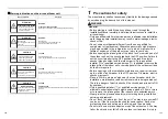
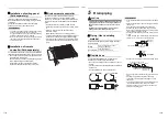
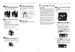
Strictly comply with the following rules to prevent damage of the indoor units and human injury.
• Do not put a heavy article on the indoor unit. (Even units are packaged)
• Carry in the indoor unit as it is packaged if possible. If carrying in the indoor unit unpacked by necessity, use buffering
cloth or other soft cloth to not damage the unit.
• To move the indoor unit, hold the hooking metals (4 positions) only.
Do not apply force to the other parts (refrigerant pipe, drain pan, foamed parts, or resin parts).
• Carry the package by two or more persons, and do not bundle it with plastic band at positions other than specified.
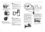
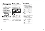
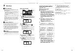
External view
13 to 20
Ceiling open dimension 580 to 594
13 to 20
Panel external dimension 620
13
to 2
0
13
to 2
0
Cei
ling o
pen
di
men
si
on
580
to 59
4
Pa
nel
ex
ter
na
l d
im
ens
io
n 62
0
External view
Unit: mm
23
+5 -0
146
191
95
147
105
55
235
105
235
320
214
256
(93) 40
132
173
257
70
Ø162
53
193
154
146
8
3
12
184
156
ØA
Cei
ling
ope
n di
men
si
on
580
to 5
94
Bottom face of ceiling
Wiring entry
(for remote control)
Uni
t ex
ter
na
l d
ime
ns
io
n 57
5
Refrigerant pipe connecting port
(Gas side)
Refrigerant pipe connecting port
(Liquid side)
Bottom face of ceiling
Unit external dimension 575
Electrical control box
Bottom face of ceiling
Ceiling panel
Hanging bolt M10 or W3/8
(Procured by locally)
Drain discharge port
(VP20)
Wiring entry
(for power supply)
Knockout for simple
OA for Ø100
4
00.
5
Hanging bolt pitch 496 to 538
Ceiling open dimension 580 to 594
Model MMU-
A
AP005 to AP012
9.5
AP015 to AP018
12.7
Indoor unit
Bottom face of ceiling
Ha
ngi
ng b
ol
t pi
tc
h 53
5
17
4.5
325
.5
Ø6.4
2.5 to 9.5
17-EN
18-EN
Содержание MMU-AP0057MH-E
Страница 29: ...EB99813301 ...