background image

FILE NO. A10-1510

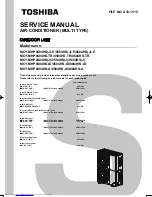
SERVICE MANUAL

AIR-CONDITIONER (MULTI TYPE)

OUTDOOR UNIT

Model name:

This service manual provides relevant explanations about new outdoor unit. 
Please refer to the following service manuals for each indoor units.

MCY-MHP0404HS(J)-E/0504HS(J)-E/0604HS(J)-E
MCY-MHP0404HS-TR/0504HS-TR/0604HS-TR
MCY-MHP0404HS(J)/0504HS(J)/0604HS(J)
MCY-MHP0404HS-ID/0504HS-ID/0604HS-ID
MCY-MHP0404HS-A/0504HS-A/0604HS-A


Service Manual No.

<4-way Cassette Type> 


(MMU-AP****H)  

A08-004

(MMU-AP***4HP*) 

(Made in Thailand model) 

SVM-13011

<2-way Cassette Type> 


(MMU-AP****WH*)  A10-007

<Concealed Duct Standard Type> 


(MMD-AP***6BHP*) 

(Made in Thailand model) 

SVM-14069

<Slim Duct Type> 


(MMD-AP024, A0274SPH*) 


A12-005

<Concealed Duct High Static Pressure Type> 


(MMD-AP***6HP*) 

(Made in Thailand model) 

SVM-15032

<High-wall Type> 


(MMK-AP***4MH*) 

(Made in Thailand model) 

SVM-09059

(MMK-AP***3H*) 

(Made in Thailand model) 

A10-034

<Console Type> 


(MML-AP****NH*) 

(Made in Thailand model) 

SVM-11036

<Ceiling Type> 


(MMC-AP***7HP*) 

(Made in Thailand model) 

SVM-13085

<Floor Standing Type> 


(MMF-AP***6H*)  

A10-1420

<Other indoor units> 


(MM*-AP*****H*)  

A10-033

A10-1510.indb   1

A10-1510.indb   1

2016/04/08   17:20:03

2016/04/08   17:20:03

Содержание MCY-0504HS(J)

Страница 1: ...Manual No 4 way Cassette Type MMU AP H A08 004 MMU AP 4HP Made in Thailand model SVM 13011 2 way Cassette Type MMU AP WH A10 007 Concealed Duct Standard Type MMD AP 6BHP Made in Thailand model SVM 14069 Slim Duct Type MMD AP024 A0274SPH A12 005 Concealed Duct High Static Pressure Type MMD AP 6HP Made in Thailand model SVM 15032 High wall Type MMK AP 4MH Made in Thailand model SVM 09059 MMK AP 3H M...

Страница 2: ...ise filter MCC 1551 27 4 5 1 Except MCY MHP HS A Model 22 4 5 2 For MCY MHP HS A Model 23 4 3 Other parts for Australia DRED Demand response enabling device 20 5 Refrigerant piping systematic drawing 28 6 Control outline 30 7 Applied control for outdoor unit 36 7 2 Priority operation mode setting 36 7 3 Applied control of outdoor unit 38 7 3 1 Optional P C board of outdoor unit installation 38 7 3...

Страница 3: ...ing of refrigerant and control lines 78 8 7 2 Function to start stop ON OFF indoor unit from outdoor unit 80 8 7 3 Checkcode clearing function 85 8 7 4 Remote controller distinction function 87 8 7 5 Pulse motor valve PMV forced open close function in indoor unit 88 8 7 6 Pulse motor valve PMV forced fixing function in outdoor unit 88 8 7 7 Solenoid valve forced open close function in outdoor unit...

Страница 4: ... C board replacement procedure MCC 1647 171 11 3 Fan IPDU P C board replacement procedure MCC 1597 173 11 4 Noise filter P C board replacement procedure MCC 1551 176 12 Exploded diagram parts list 178 10 Outdoor unit parts replacement methods 152 9 7 Sensor characteristics 147 9 8 Pressure sensor output check 150 3 ...

Страница 5: ... been trained and is thus thoroughly acquainted with the knowledge related to this work s The qualified service person who is allowed to work at heights has been trained in matters relating to working at heights with the air conditioners made by Toshiba Carrier Corporation or alternatively he or she has been instructed in such matters by an individual or individuals who have been trained and is th...

Страница 6: ...tric shock Work done at heights 50 cm or more Helmets for use in industry Transportation of heavy objects Shoes with additional protective toe cap Repair of outdoor unit Gloves to provide protection for electricians n o i t a n a l p x E n o i t a c i d n I DANGER Indicates contents assumed that an imminent danger causing a death or serious injury of the repair engineers and the third parties when...

Страница 7: ... operate unit with grille removed Stop the unit before the servicing CAUTION High temperature parts You might get burned when removing this panel CAUTION Do not touch the aluminium fins of the unit Doing so may result in injury CAUTION BURST HAZARD Open the service valves before the operation otherwise there might be the burst Refrigerant recovery during operation is prohibited CAUTION Do not clim...

Страница 8: ...osition and contact a qualified service person Take steps to ensure that the power will not be turned on by marking out of service near the circuit breaker for instance until qualified service person arrives Continuing to use the air conditioner in the trouble status may cause mechanical problems to escalate or result in electric shocks or other failure Electric shock hazard When you access inside...

Страница 9: ...en transporting the air conditioner use a forklift and when moving the air conditioner by hand move the unit with 5 people When executing address setting test run or troubleshooting through the checking window on the electrical control box put on insulated gloves to provide protection from electric shock Otherwise you may receive an electric shock Do not touch the aluminum fin of the outdoor unit ...

Страница 10: ...n the refrigerant will be mixed in the refrigerating cycle Failure to purge the air completely may cause the air conditioner to malfunction Do not charge refrigerant additionally If charging refrigerant additionally when refrigerant gas leaks the refrigerant composition in the refrigerating cycle changes resulted in change of air conditioner characteristics or refrigerant over the specified standa...

Страница 11: ...and etc and moreover if there is leak of refrigerant at connecting section of pipes the air is sucked and causes further abnormal high pressure resulted in burst or injury Check after reinstallation Only a qualified installer or qualified service person is allowed to relocate the air conditioner It is dangerous for the air conditioner to be relocated by an unqualified individual since a fire elect...

Страница 12: ...to use the company specified products for the separately purchased parts Use of non specified products may result in fire electric shock water leakage or other failure Have the installation performed by a qualified installer Do not supply power from the power terminal block equipped on the outdoor unit to another outdoor unit Capacity overload may occur on the terminal block and may result in fire...

Страница 13: ...ovisions of the Machinery Directive Directive 2006 42 EC and the regulations transposing into national law NOTE This declaration becomes invalid if technical or operational modifications are introduced without the manufacturer s consent 11 Specifications Cooling Heating 49 50 51 49 50 51 49 50 51 52 53 54 52 53 54 52 53 54 127 127 127 127 127 127 127 127 127 Model Sound Pressure level dBA Weight k...

Страница 14: ...hers do not mix in because pipes are affected by impurities such as water oxide scales oil etc Use the clean pipes Be sure to brazing with flowing nitrogen gas Never use gas other than nitrogen gas 4 For the earth protection use a vacuum pump for air purge 5 R410A refrigerant is azeotropic mixture type refrigerant Therefore use liquid type to charge the refrigerant If using gas for charging compos...

Страница 15: ...eak detector Checking gas leak Exclusive to R410A Vacuum pump Vacuum drying Usable if a counter flow preventive adapter is attached e l c i t r a g n i t s i x E 2 2 R g n i y r d m u u c a V w o l f r e t n u o c h t i w p m u p m u u c a V e z i s g n i t s u j d a y b e l b a s U s e p i p f o g n i s s e c o r p e r a l F l o o t e r a l F e l c i t r a g n i t s i x E 2 2 R s e p i p f o g n ...

Страница 16: ...ls on these models read the owner s manuals that come with the indoor units Power supply Power supply Single phase 220 240V 50Hz 220V 60Hz Cooling capacity kW 1 Heating capacity kW 1 4HP MCY MHP0404HS E MCY MHP0404HSJ E MCY MHP0404HS TR MCY MHP0404HS ID MCY MHP0404HS A MCY MHP0404HS MCY MHP0404HSJ 12 1 12 5 Corresponding HP 5HP MCY MHP0504HS E MCY MHP0504HSJ E MCY MHP0504HS TR MCY MHP0504HS ID MCY...

Страница 17: ...4 0 1 Y H M B R r e d a e h g n i h c n a r b 4 E 3 8 0 1 Y H M B R r e d a e h g n i h c n a r b 8 Model type Indoor unit capacity type Appearance 005 to 014 type E 3 6 3 0 V M P M B R 015 to 027 type E 3 0 9 0 V M P M B R RBM BY55E t n i o j g n i h c n a r b e p a h s Y 16 ...

Страница 18: ...ting port Liquid side connecting port Refrigerant pipe 30 29 445 476 Knockout for downward piping 54 port Air outlet port Air inlet Air inlet port 235 110 30 85 245 442 25 23 155 45 6 Drain hole ĭ20 88 58 490 1235 130 159 R 6 5 9 52 9 52 15 88 15 88 19 05 9 52 9 52 9 52 19 05 15 88 15 88 100 159 R 5 0 305 134 120 R 6 0 16 16 16 390 Slit hole for piping 380 Center of gravity Center of gravity 490 C...

Страница 19: ... 0504HS J E 0604HS J E MCY MHP0404HS TR 0504HS TR 0604HS TR MCY MHP0404HS J 0504HS J 0604HS J MCY MHP0404HS ID 0504HS ID 0604HS ID COMPRESSOR IPDU BOARD I F P C BOARD NOISE FILTER P C BOARD FAN IPDU BOARD 㻞㻞㻜㻌㻙㻌㻞㻠㻜㼂䡚㻘㻌㻡㻜㻴㼦 㻌 㻞㻞㻜㼂䡚㻘㻌㻢㻜㻴㼦 18 ...

Страница 20: ... CM P PMV T6 3A 250V T6 3A 250V 25 0A 250V T6 3A 250V 50 0A 250V High pressure switch Transformer TT 02 T01 MCC 1653 DEMAND P C BOARD Fuse Demand MCC 1653 F100 T3 15A 250V 0 3 FM2 MS 1 5 1 5 1 1 1 1 1 5 MS CM 8 9 5 8 1 䢳 䢢䢢䢷䢲䣊䣼䢢䢴䢴䢲䢯䢴䢶䢲䣘 0 1 1 1 1 1 1 MS FM1 3 5 5 1 1 8 3 7 1 7 1 0 0 5 POWER UpperSide SUPPLY LowerSide IPDU BOARD IPDU BOARD COMPRESSOR 0 1 1 1 1 5 1 5 5 5 3 We 8 䢶 䢵 䢴 䢶 䢳 䢵 䢴 䢳 䢶 䢵 䢴...

Страница 21: ... e d o M n o i t a c i f i c e p S l e d o M o N 1 AC600V 60A 3P JXO 6003 Power supply terminal block 1 2 AC30V or no more than DC42V 1A 6P HP T4053 1 4PS2 Communication terminal block MCC 1639 9 45mH 16A 3 CH 57 DN Reactor For comp 10 11 12 13 14 15 16 17 18 19 4 5 6 7 8 9 e m a N 20 C 80 C Ambient temp range Pipe temp sensor TL 15A AC250V GDT250V15A Fuse MCC 1597 10A DC600V P C board FSBF10CH60B...

Страница 22: ... unit SV4 valve SV2 valve SV5 valve 4 way valve Low pressure sensor TS sensor High pressure sensor High pressure sw High pressure Check joint Low pressure Check joint TD sensor TL sensor Pulse Motor Valve PMV sensor sensor TO TE 21 ...

Страница 23: ...nverter assembly 4 5 1 Except MCY MHP HS A Model Fan IPDU P C board MCC 1597 Communication terminal block Interface P C board MCC 1639 Power supply terminal block Noise Filter P C board MCC 1551 Comp IPDU P C board MCC 1647 22 ...

Страница 24: ...Fan IPDU P C board MCC 1597 Communication terminal block Interface P C board MCC 1639 Power supply terminal block Noise Filter P C board MCC 1551 Comp IPDU P C board MCC 1647 Demand response P C board MCC 1653 Transformer TT 02 2 R 23 ...

Страница 25: ... CN501 PMV 1 output CN300 UART communication CN600 Dyna Doctor connecting terminal CN800 SW 30 For communication wire between outdoor unit and central remote controller SV 5 CN314 SV 4 CN312 SV 2 CN311 4 way valve output CN317 Power supply input CN400 Case thermo CN308 For communication wire between indoor and outdoor unit CN02 short CN10 connector When the central remote controller is connected t...

Страница 26: ...k CN201 Red Compressor output U phase UART communication CN851 Red Power supply Input Neutral CN05 Black and Red Power supply Input Reactor CN12 Red Power supply output Reactor CN11 Black Power supply output Reactor CN500 Black High pressure switch input CN511 Red Power supply Input DC280V Output CN21 White CN04 Black Power supply Input Live 25 ...

Страница 27: ...pper fan and lower fan CN750 White Fan motor output Lower fan CN700 Blue Fan motor output Upper fan CN505 Red UART communication CN504 Blue UART communication CN502 White DC280 V input CN500 Red Power supply input and reactor connecting 26 ...

Страница 28: ...ise filter MCC 1551 L01 Line Filter CN02 White Power supply input Neutral CN04 White Power supply output Neutral CN03 Black Power supply output Live CN08 White Power supply output CN01 Black Power supply input 27 ...

Страница 29: ...lve SV5 Strainer PMV Strainer Sensor TL Liquid side packed valve Gas side ball valve Compressor Strainer Sensor TD 4 Way valve Sensor TS Solenoid valve SV4 Solenoid valve SV2 Capillary tube Check joint Muffler High pressure sensor Check joint Low pressure sensor Accumulator High pressure SW Capillary tube Liquid Tank 28 ...

Страница 30: ...0 Green 1 Controls defrost in heating operation 2 Controls outdoor fan in heating operation TL Connector CN523 White 1 Detects subcool in cooling operation TO Connector CN507 Yellow 1 Detects outside temperature Pressure sensor High pressure sensor Connector CN501 Red 1 Detects high pressure and controls compressor capacity 2 Detects high pressure in cooling operation and controls the fan in low a...

Страница 31: ...tate or upon being turned off normally or shut down due to an abnormality 2 Outdoor fan control 1 Cooling fan control 1 Outdoor fan speed mode is controlled on the basis of measurements provided by the PD pressure sensor 2 For a specified period after the start of cooling operation the outdoor unit controls outdoor fan speed mode on the basis of measurements provided by the PD pressure sensor Avai...

Страница 32: ...ndition 5 Defrosting control reverse defrosting method 1 Defrosting commencement conditions During heating operation the cumulative duration of operation in which TE sensor temperature falls below frost formation temperature is measured and when this reaches 55 minutes defrosting control is introduced Just after startup or upon changeover from cooling to heating the target cumulative duration is 2...

Страница 33: ...efrosting operation or cooling operation The speed of the compressor rises to 82 rps or more 3 SV2 low pressure release control This control function is aimed at preventing a rapid fall in pressure during transient operation The control is always provided except during periods of stoppage or thermostat OFF 1 Control details heating When PS pressure becomes 0 1 MPa SV2 is opened When PS pressure be...

Страница 34: ...decreases and current release control values via the interface P C board The main control functions of the IPDU P C board are described below 1 Current release control To prevent inverter input current from exceeding the specified value output frequency is controlled with AC input current as detected by T611 mounted on the A3 IPDU P C board Current control values for various outdoor units are show...

Страница 35: ...ure count is cleared 3 If the failure count reaches 8 the check code is confirmed as final The compressor stops when the compressor case thermostat is activated Whenever this condition occurs 1 count is added to the system failure count After a period of 5 minutes the compressor is reactivated and the failure count cleared if the operation continues without further failure for a period of 10 minut...

Страница 36: ...se Motor Valve 1 When the power is turned on PMVs generate a tapping sound as they are initialized If this sound is not heard there is a possibility of faulty PMV operation However in a noisy environment it may simply be drowned out by ambient noise 2 Do not separate the actuator head section from any PMV during operation It may result in an inaccurate opening 3 When transporting relocating the se...

Страница 37: ...eration priority given to the operation mode with the largest share of units in operation ON ON Priority indoor unit priority given to the operation mode of the specific indoor unit set up for priority operation 7 Applied control for outdoor unit 7 2 Priority operation mode setting Purpose characteristics This function is used when connecting a duct to the discharge port of an outdoor unit as part...

Страница 38: ...n so that the position of this unit can be confirmed 3 Use the button to select the CODE No 04 4 Use the button to select the SET DATA 0001 Priority set 0001 No priority set 0000 5 Push the button The setup is finished when the display changes from flashing to steady 6 Upon finishing the setup push the button This finalizes the setting When the button is pushed the display goes blank and the syste...

Страница 39: ...n the electrical box Use the supports to install the optional P C boards Optional P C board Up to a total of two boards TCB PCIN4E left side TCB PCDM4E right side TCB PCMO4E both side Optional P C board for Australia model A are two boards TCB PCIN4E right side TCB PCMO4E right side Wiring connections 1 Refer to the details on the wiring diagrams 2 Be sure to use the shield wire to prevent noise t...

Страница 40: ...ontrol Enhanced Functions CN513 blue SW07 1 2 l o r t n o c n a f l l a f w o n S 3 CN509 black l o r t n o c F F O N O r e t s a m l a n r e t x E 4 CN512 blue 5 Night operation sound reduction control CN508 red l o r t n o c n o i t c e l e s e d o m n o i t a r e p O 6 CN510 white t u p t u o n o i t a r e p O r o r r E 7 CN511 green J20 Operation mode selection control forced choice CN510 whit...

Страница 41: ...or unit has been removed Power peak cut control P C board SW1 SW2 L1 Interface P C board of outdoor unit N O 1 t i B 7 0 W S F F O 1 t i B 7 0 W S Power peak cut control ON signal received ON OFF ON 0 forced stop 60 capacity upper limit regulated Power peak cut control OFF signal received OFF ON OFF 100 normal operation 100 normal operation Outdoor unit L1 Display lamp ensuring power peak cut cont...

Страница 42: ...necting a conductive load e g relay coil to the display relay load insert a surge killer CR for an AC power supply or a diode for preventing back electromotive force for a DC power supply on the bypass circuit Jumper wire J20 Input SW1 y a l e r r o t a c i d n I 1 t i B 7 0 W S 1 L N O 1 t i B F F O 1 t i B Cut 0 forced stop 60 capacity upper limit regulated 100 normal operation 100 normal operat...

Страница 43: ...SW2 terminals simultaneously 2 Be sure to provide a contact for each terminal External signal No voltage pulse contact Terminal Input signal Operation COOL SW1 Snowfall fan control Turns on outdoor unit fan Normal operation Cancels control Terminal Input signal Operation COOL SW1 Turns on all indoor units HEAT SW2 Turns off all indoor units Outdoor unit COM Outdoor unit interface PCB Optional PCB ...

Страница 44: ...duction Position of noise measuring device 1 m from the front face of the set and 1 5 m above ground in anechoic Terminal Input signal Operation COOL SW1 Night time control Normal operation Outdoor unit base unit Relative to maximum capacity Cooling Heating Model 0404 approx 90 approx 95 Model 0504 approx 80 approx 80 Outdoor unit COM Outdoor unit interface PCB Optional PCB Connection cable Locall...

Страница 45: ...nits operating in a mode different from the selected operation mode can be changed by changing the status of a jumper wire J01 provided on the interface P C board of outdoor unit Jumper wire Description of intervention J01 connected factory default All indoor units operating in a mode different from the selected operation mode prohibited mode indoor units become non priority units thermostat OFF T...

Страница 46: ...nd K2 insert a surge killer CR for an AC power supply or a diode for preventing back electromotive force for a DC power supply on the bypass circuit Electrical Rating 220 240 VAC 10 mA or more 1 A or less 24 VDC 10 mA or more 1 A or less non conductive load C1 Connector cable 1 CN511 Connector on Interface side green K1 K2 Relays L1 Failure indication Lamp L2 Operation indication Lamp OUTPUT1 Fail...

Страница 47: ... Demand P C board DRM1 DRM2 DRM3 COM Connect the wiring to the demand P C board as shown in This model is valid only for demand response mode DRM1 Wires for indoor outdoor communication Outline of DRED wiring CN101 CN106 CN102 CN100 COM DRM1 DRM2 DRM3 L Trans former DRED Locally procured Power supply MCC 1653 DEMAND P C BOARD MCC 1551 NOISE FILTER P C BOARD U1 To central controller To indoor unit ...

Страница 48: ...ssion connector CN104 CN105 CN106 DRC signal reception connector CN01 Transformer input connector CN101 Power supply protection fuse F100 250V 3 15A Power supply input connector CN100 Transformer output connector CN102 DB100 LED indicator D101 47 ...

Страница 49: ...ation Check that the main power supply is turned on Set up the addresses Test operation END This main power supply check shall be done before operation switch turns ON This main power supply check shall be done before operation switch turns ON Start the address setup in the outdoor indoor units Note Operation does not start simply by powering on Carry out a test operation Check air blowing and coo...

Страница 50: ...controller or optional devices If connect a relay connector CN10 to CN02 will connected communication line U1 U2 and U3 U4 The connected U1 U2 and U3 U4 brings incorrect refrigerant line address setting k c e h C s m e t i k c e h c n i a M 1 Are the indoor and outdoor communication lines of the outdoor unit connected to the U1 U2 terminals 2 Relay connector CN10 which is mounted on the interface ...

Страница 51: ...urn off SW30 bit 2 of the outdoor unit for other refrigerant lines 8 4 3 Address setup procedure 5 Is the end terminal of the shield wire earthed 6 When the refrigerant line and the central control system of the DI SDI series are connected Are Network adapter TCB PCNT30TLE2 correctly connected When the DI SDI series operates with group twin or triple operation are the adapters connected to the hea...

Страница 52: ...units supplied collectively Is it grounded to earth Is the insulation resistance sufficient 10 M M r e h g i h r o or higher V in 220 240 V 10 h t i w t n e i c i f f u s e g a t l o v r e w o p n i a m e h t s I Is the diameter of connecting pipe correct Is the branch kit correct Is the water drain of the indoor unit arranged so that it flows without accumulation Is the heat insulation of pipes s...

Страница 53: ...t of refrigerant by pipe length A Standard amount of refrigerant kg m Pipe diameter on the liquid side Compensation by outdoor HP Table 2 B Next refer to the following table for the corrective amount of refrigerant by outdoor HP B Table 2 Compensation by outdoor HP Lastly add the additional amount of refrigerant by pipe length A and the corrective amount of refrigerant by outdoor HP B This is the ...

Страница 54: ... Display check on the remote controller in the case of a wired remote controller Check that a frame as shown in the following figure at left is displayed on the LC display section of the remote controller If no frame is displayed as shown in the above figure at right the remote controller does not have a normal supply of power check the following items Check the power supply of the indoor unit Che...

Страница 55: ... the 7 segment display B on the interface P C board of the outdoor unit in the system where the address is to be set up 4 Address setup start Confirm the items in 8 4 3 Address setup procedure and then set up the address according to the operation procedure Be careful to note that the setup operation may differ in group control and central control systems Note The address cannot be set up if switc...

Страница 56: ...oup before setting addresses If you set the unit addresses of each line separately each line s header indoor unit is set separately In that case the CODE No L03 Indoor outdoor unit overlap is indicated as running starts Change the group address to make one unit the outdoor unit using wired remote controller d d A o t o g Single refrigerant line l o r t n o c l a r t n e c o N ress setting procedur...

Страница 57: ...use a same address as another system refrigerant line or a 1 to 1 system side Interface P C board on the outdoor unit Line address switches on the outdoor interface P C board switch on switch off Example Controlling 2 or more refrigerant lines as a group System wiring diagram Outdoor Indoor Indoor Indoor Indoor Outdoor Remote controller Group control Line address Not used for setup of line address...

Страница 58: ... i h s a l f s t r a t s n o i t a c i d n i e h t r e t f A t i l s n i a m e r d n a s p o t s g n i h s a l f e h t n e h W on the display the setting is complete 7 Repeat steps 4 to 6 for other refrigerant lines 8 After completing address setting of all systems turn off DIP switch 2 of SW30 on the interface P C boards of all the outdoor units connected to the same central control except the un...

Страница 59: ...entral control address refer to the installation manuals of the central control devices 7 segment display Outdoor unit interface P C board SW30 Outdoor units are connected to the same central control except the outdoor unit with the smallest line address number 58 ...

Страница 60: ...ndoor outdoor communication line and central control line ON Set to OFF after setting addresses Set to OFF after setting addresses ON Relay connector Connect after setting addresses Connect after setting addresses Connect after setting addresses Open Line system address 1 1 2 2 3 1 2 1 2 1 s s e r d d a t i n u r o o d n I 0 2 1 0 0 s s e r d d a p u o r G 2 U 1 U B A 2 U 1 U 2 U 1 U B A B A A 2 U...

Страница 61: ...nnect a wired remote controller to the target unit directly before address setting Pair the indoor unit to set and the remote controller one to one Turn on the power 1 Push and hold the and buttons at the same time for more than 4 seconds LCD starts flashing Line system address 1 1 1 2 2 Indoor unit address 1 2 3 1 2 Group address 1 Header unit 2 Follower unit 2 Follower unit 2 Follower unit 2 Fol...

Страница 62: ...resses using the remote controller These 2 address numbers cannot be used on outdoor units and the CODE No E04 Indoor outdoor communication failure will appear if they are mistakenly used 2 If you set addresses to indoor units in 2 or more refrigerate lines manually using the remote controller and will control them centrally set the outdoor unit of each line as below Set a line address for the out...

Страница 63: ...ile the units are running 1 Push the button if the units stop 2 Push the button left side of the button A unit numbers is indicated on the LCD it will disappear after a few seconds The indicated number shows the line address and indoor unit address of the unit When 2 or more indoor units are connected to the remote controller group controlled units a number of other connected units appears each ti...

Страница 64: ...for central control Execute it while the units are stopped You can check indoor unit addresses and positions of the indoor units in a single refrigerant line When an outdoor unit is selected the indoor unit numbers of the refrigerant line of the selected unit are indicated one after another and the fan and louvers of the indicated indoor units are activated 1 Push and hold the TIME and buttons at ...

Страница 65: ...If 2 or more indoor units are controlled in a group the first indicated UNIT No is that of the head unit 2 Push the button left side of the button repeatedly to select an indoor unit number to change if 2 or more units are controlled in a group The fan and louvers of the selected indoor unit are activated The fan of the selected indoor unit is turned on 3 Push the TEMP buttons repeatedly to select...

Страница 66: ...it exists on the line Push button and select another line following step 2 Execute it while the units are stopped 1 Push and hold the TIME and buttons at the same time for more than 4 seconds At first the line 1 and CODE No Address Change are indicated on the LCD display 2 Push left side of the button and buttons repeatedly to select a line address 3 Push the button The address of one of the indoo...

Страница 67: ...a wired remote controller Set the line address indoor unit address and group address to 0099 using a wired remote controller For the setting procedure refer to the address setting procedures using the wired remote controller on the previous pages Method 2 Clearing all the indoor unit addresses on a refrigerate line at once from the outdoor unit 1 Turn off the refrigerant line to reset to the facto...

Страница 68: ...successfully If the 7 segment display indicates A d n G the outdoor unit may still connected with other refrigerant lines Check the connection of the relay connectors between U1 U2 and U3 U4 NOTE Take care to carry out the procedure above correctly otherwise addresses in other refrigerate lines may also be cleared 5 Set the addresses again after finishing the clearance s e s s e r d d a e l b a r ...

Страница 69: ...he refrigerant line for which an address is to be set up After approximately 1 minute check that U 1 is displayed on the 7 segment display 4 Execute the following operation on the interface P C board of the outdoor unit AUTO1 AUTO2 AUTO3 AUTO9 is counted and displayed on the 7 segment display 5 When U 1 is displayed on the 7 segment display the setup operation finished Turn off the indoor outdoor ...

Страница 70: ...r resistor SW30 bit 2 of the outdoor unit with the smallest line address number in the central control turned on 3 Is the terminator resistor SW30 bit 2 of the outdoor unit except for the line with the smallest central control line address turned off Line address 4 Are addresses in the line address SW13 SW14 not duplicated in each refrigerant line Central remote controller 4 Indoor unit To other r...

Страница 71: ...ation circuit trouble Detected by outdoor side Check SW30 bit 2 of the outdoor unit No connection between multiple refrigerant lines SW30 bit 2 is on Check the communication connector between indoor and outdoor unit Transmission circuit trouble at the interface side P C board failure Replace the interface P C board E06 After address setup communication from all the indoor units is interrupted unde...

Страница 72: ...utdoor the unit that does not respond to the indoor remote controller Modify the wiring Line address and indoor address are not set the unit that does not respond to the indoor remote controller Set up the address The power of the outdoor unit of the group is not turned on in indoor group control the unit that does not respond to the indoor remote controller Turn on the power Group address is set ...

Страница 73: ...group operation from an indoor remote controller The indoor remote controller is not connected with wire Miswiring of the indoor remote controller Using the main indoor remote controller connected to a group start a test operation specify the unit that is not operating the unit not connected to the group and then check the wiring Indoor remote controller communication circuit trouble If 220 240 V ...

Страница 74: ...he remote controller remove the cause of the check code referring to Check code and check position displayed on remote controller and outdoor unit Select the Fan operating mode Is air discharged from the discharge port of the indoor unit Check the indoor fan fan motor and fan circuit Is the sound normal Check the postions around the fan YES YES Normal Check every indoor unit in turn 73 ...

Страница 75: ...nit enters test operating mode 2 Push the button 3 Using the Select Mode button select the COOL or HEAT operating mode Do not use an operating mode other than COOL or HEAT Temperature adjustment is unavailable during test operation Check code is detected as usual 4 When the test operation has finished push the button to stop the operation The same display as in procedure 1 appears in the display s...

Страница 76: ...eard and the operation changes to a forced cooling operation After approx 3 minutes a cooling operation starts forcedly Check cool air starts blowing If the operation does not start check wiring again To stop a test operation push Temporary button once again approx 1 second Check wiring piping of the indoor and outdoor units in forced cooling operation Start Push Temporary operation button The ope...

Страница 77: ...ter powering on or stopping operation Note After powering on it may require up to 10 minutes to start the operation due to the initial communications of the system Check the operating status of the compressor Check the direction of the louver Execute a test operation using Start Stop Function of the Indoor Unit from Outdoor Unit in the Service Support Function section Check power voltage of the ma...

Страница 78: ...ions refer to 2 This compressor is driven with a 4 pole motor The value of the compressor frequency rps measured with a clamp meter at the compressor lead line is two times the rotation count rps of the compressor The temperature of the indoor heat exchanger TC indicates TCJ sensor temperature when cooling and TC2 sensor temperature when heating respectively 2 Criteria for operating pressure Crite...

Страница 79: ...h the expected system capacity 7 segment display System horsepower 7 segment display No of connected outdoor units No of units with cooling thermostat ON 7 segment display No of connected outdoor units No of units with heating thermostat ON 7 segment display Cooling Heating Check No of indoor units No of units with cooling thermostat ON Set the rotary switches SW01 SW02 SW03 on the interface P C b...

Страница 80: ... switch SW05 on the interface P C board of the outdoor unit for 2 seconds or more The indoor address in which check code is being detected is displayed on 7 segment display B If there are multiple indoor address in which check code is being detected they are successively exchanged and displayed When SW05 is turned on again the display returns to display of No of units 7 segment display Address dis...

Страница 81: ...econds Batch stop Stops all the connected indoor units collectively Setup Set SW01 SW02 SW03 to 2 7 1 and press SW05 Release Return SW01 SW02 SW03 to 1 Section A C H Section B 00 00 is displayed on Section B for 5 seconds 4 Individual start Starts the specified indoor unit Notes The contents follow to the setup of remote controller The other indoor units keep the status as they are Setup Set SW01 ...

Страница 82: ... 2 seconds or more Test run is displayed on the remote controller of the indoor unit to be operated Check that C is displayed on 7 segment display B on the interface P C board of the outdoor unit Return SW01 SW02 SW03 on the interface P C board of the outdoor unit to 1 1 1 or press the push switch SW05 for 2 seconds or more Start Operation check Stop End NOTE The test operation returns to the norm...

Страница 83: ... 2 seconds or more Test run is displayed on the remote controller of the indoor unit to be operated Check that H is displayed on 7 segment display B on the interface P C board of the outdoor unit Start Operation check Stop End Return SW01 SW02 SW03 on the interface P C board of the outdoor unit to 1 1 1 or press the push switch SW05 for 2 seconds or more NOTE The test operation returns to the norm...

Страница 84: ...peration return the rotary switches SW01 SW02 SW03 on the interface P C board of the outdoor unit to 1 1 1 Start Stop End If a check code is already displayed with SW01 SW02 SW03 being 1 1 1 return the status to normal one according to troubleshooting and then execute a test operation The unit which is not given with priority by heating priority control cooling priority control and selection of co...

Страница 85: ... Match the rotary switches on the interface P C board of the outdoor unit to the following table 7 segment display Address display of corresponding indoor unit Press the push switch SW04 on the same board for 2 seconds or more If pressed continuously for 10 seconds or more the operation changes to the individual test operation 7 segment display Address display of corresponding indoor unit 11 is di...

Страница 86: ...1 Change the mode to service monitor mode by pushing buttons simultaneously for 4 seconds or more 2 Using buttons set CODE No to FF 3 The display in Section A in the following figure is counted with interval of 5 seconds as 0005 0004 0003 0002 0001 0000 When the count arrives 0000 the check code is cleared However counting from 0005 is repeated on the display 4 When button is pushed the status ret...

Страница 87: ...ay 3 Clearing check code by resetting power This function is provided to clear check code in a system by resetting the power of all the outdoor and the indoor units As same as the clearing method by the interface P C board check codes of both the outdoor and the indoor units are once cleared and check code detection is performed again Method 1 Be sure to reset power of both the outdoor and the ind...

Страница 88: ...ows Set SW01 SW02 SW03 to 2 4 1 Press the push switch SW04 on the same board for 2 seconds or more 7 segment display Checking display of the connected remote controller flashes Press the push switch SW05 on the interface P C board of the outdoor unit for 2 seconds or more Operation Check the connected remote controller End Other end conditions 1 10 minutes have passed 2 SW01 SW02 or SW03 changed t...

Страница 89: ...g degree adjustment of pulse motor valve PMV1 By setting the switch PMV can be fixed 2 minutes open fully open half or close fully the opening of the pulse motor valve Operation Open fully Set the switches SW01 SW02 SW03 on the interface P C board of the outdoor unit to 2 1 8 and press SW04 for 2 seconds or more 7 segment display appears as below P View PMV opening degree the Open fully of this mo...

Страница 90: ...ch solenoid valve is as shown below NOTE 1 Display in 7 segment display B is exchanged just when the number of SW02 has been changed on the other hand the solenoid valve output is exchanged when SW02 has been kept with the same number for 5 seconds or more NOTE 2 The mark O in the table indicates that the corresponding solenoid valve is forcedly turned on NOTE 3 The mark in the table indicates tha...

Страница 91: ...ed in 7 segment display A keep pressing the switch SW04 for 2 seconds or more 3 When 31 is displayed in 7 segment display B the fan starts operation Max mode operation 4 After that by changing the setup number of the switches SW02 and SW03 7 segment display B and the fan mode are changed Mode output pattern of the fan is as follows Clear This function is cleared by one of the following operations ...

Страница 92: ...04 on the interface P C board for 1 second or more The mode changes to the TO sensor value fix manual mode 3 As shown in the following table TO sensor value can be fixed by setting the rotary switch SW02 on the interface P C board Clear Return SW01 SW02 SW03 on the interface P C board in the outdoor unit to 1 1 1 NOTE If operated with TO sensor fixed by this function the system control operation o...

Страница 93: ...er the leaks are being detected It also can be confirmed by remote control monitor function Refer to 8 7 12 Monitor function of remote controller switch 2 Clearing the initial value If the system is changed e g indoor units are increased replaced outdoor units are moved or refrigerant is refilled increased it is necessary to clear the initial value that had been saved Make sure that the compressor...

Страница 94: ... g n i t a e H H 6 n o i t c n u f F F O N O p o t s t r a t s e v i t c e l l o c r o o d n I H C 7 E 6 1 r Check code clear function 1 16 3 H r Solenoid valve forced open close function 2 4 5 F d Fan forced operation function 2 15 t o Outside temperature sensor manual adjustment function 16 1 16 1 0 1 1 6 Indoor No 1 to 16 unit Indoor individual start stop ON OFF function 2 1 7 3 2 Indoor No 17 ...

Страница 95: ...rol 1 C 0024 24 C 01 Room temperature Remote controller 1 C C 1 A T e r u t a r e p m e t n o i t c u s r o o d n I 2 0 C 1 J C T e r u t a r e p m e t l i o c r o o d n I 3 0 C 1 2 C T e r u t a r e p m e t l i o c r o o d n I 4 0 C 1 1 C T e r u t a r e p m e t l i o c r o o d n I 5 0 06 Indoor discharge temperature TF 1 1 C s l p 0 0 5 1 0 5 1 0 s l p 0 1 1 g n i n e p o V M P r o o d n I 8 0 S...

Страница 96: ...N 1 A compressor would not start Could it just be the 3 minute delay period 3 minutes after compressor shutdown Could it just be the air conditioner having gone thermostat OFF Could it just be the air conditioner operating in fan mode or put on the timer Could it just be the system going through initial communication 2 An indoor fan would not start Could it just be cold air discharge prevention co...

Страница 97: ...onse mode Description DRM1 Compressor off e l b a l i a v a t o N 2 M R D DRM3 Not available Each condition is within the operating condition but the compressor does not work Operating conditions of air conditioner Diagnosis when compressor does not work Disconnect the connecting wiring of DRED Remove wiring of CN106 on DRED P C board Normal Demand operation or DRED is failed Inverter Assembly is ...

Страница 98: ...ard Exchange of Demand P C board Fuse F100 is melted NO NO YES Exchange of transformer exchange of Demand P C board YES Exchange of transformer YES Short circuit is found between 1 and 2 pins of connector connected to CN102 of transformer Take off wiring of CN102 Short circuit is found between and of DB100 NO 97 ...

Страница 99: ...on between indoor header and follower unit Periodic communication between indoor header and follower units cannot be maintained T L A 1 0 F Indoor heat exchanger temperature sensor TCJ trouble Heat exchanger temperature sensor TCJ has been open short circuited T L A 2 0 F Indoor heat exchanger temperature sensor TC2 trouble Heat exchanger temperature sensor TC2 has been open short circuited T L A ...

Страница 100: ...9 0 E Both remote controllers have been set as master remote controller in two remote controller control alarm and shutdown for outdoor unit and continued operation for follower unit Check code Display of receiving unit check code of Description Typical trouble site TCC LINK central control Outdoor 7 segment display Indicator light block Sub code Flash C05 No indication when main remote controller...

Страница 101: ...g Indoor unit from other refrigerant line is detected while indoor automatic address setting is in progress T L A 4 0 F 4 0 F Outdoor discharge temperature sensor TD trouble Outdoor discharge temperature sensor TD has been open short circuited T L A 6 0 F 6 0 F Outdoor heat exchanger temperature sensor TE trouble Outdoor heat exchanger temperature sensors TE have been open short circuited T L A 7 ...

Страница 102: ...igerant line due to detection of overflow detected by indoor unit T L A 3 1 P 3 1 P Outdoor liquid backflow detection trouble State of refrigerant cycle circuit indicates liquid backflow operation P15 01 TS condition 02 TD condition n o i t c e t e d k a e l s a G T L A 5 1 P Outdoor suction temperature sensor TS detects sustained and repeated high temperatures that exceed standard value T L A 9 1...

Страница 103: ...tection circuit detects overcurrent H02 H02 Compressor trouble lockup Compressor lockup is detected H03 H03 Current detection circuit trouble Abnormal current is detected while inverter compressor is turned off T L A 7 0 P 7 0 P Heat sink overheating trouble Temperature sensor built into IGBT TH detects overheating P22 0 IGBT short circuit 1 Position detection circuit trouble 3 Motor lockup troubl...

Страница 104: ... Procedure To be performed when system at rest 1 Invoke the SERVICE CHECK mode by pressing the buttons simultaneously and holding for at least 4 seconds The letters SERVICE CHECK light up and the check code 01 is displayed indicating the check code history This is accompanied by the indoor unit No to which the error history is related and a check code 2 To check other check code history items pres...

Страница 105: ...down 1 Push the buttons simultaneously and hold for at least 4 seconds 2 The letters SERVICE CHECK light up and the check code 01 is displayed 3 When a group No is selected blinking if there is a check code history the UNIT No and the latest check code history information are displayed alternately During this procedure the temperature setting feature is unavailable 4 To check other check code hist...

Страница 106: ...ny indoor units connected overloading E20 Detection of refrigerant piping communication trouble during automatic address setting E31 IPDU communication trouble P01 Indoor AC fan motor trouble P10 Indoor overflow trouble P12 Indoor DC fan motor trouble P13 Outdoor liquid backflow detection trouble P03 Outdoor discharge TD temperature trouble P05 Open phase power failure Inverter DC voltage Vdc trou...

Страница 107: ...Protective shutdown of outdoor unit L03 Duplicated indoor group outdoor unit L05 Duplicated priority indoor unit as displayed on priority indoor unit L06 Duplicated priority indoor unit as displayed on indoor unit other than priority indoor unit L07 Connection of group control cable to stand alone indoor unit L08 Indoor group address not set L09 Indoor capacity not set L04 Duplicated outdoor refri...

Страница 108: ...daptor Check remote controller and network adaptor wiring E04 Indoor unit Indoor outdoor communication circuit trouble detected at indoor end Stop of corresponding unit Indoor unit is not receiving signal from outdoor unit Check order in which power was turned on for indoor and outdoor units Check indoor address setting Check indoor outdoor tie cable Check outdoor terminator resistor setting SW30 ...

Страница 109: ...o overloading detected setting No overloading detected setting method Turn on SW09 Bit 2 on I F P C board of outdoor unit More than 13 indoor units are connected Check capacities of indoor units connected Check combined HP capacities of indoor units Check HP capacity settings of outdoor units Check No of indoor units connected Check for trouble in outdoor P C board I F E18 Indoor unit Trouble in c...

Страница 110: ...nnector Check resistance characteristics of TL sensor Check for trouble in outdoor P C board I F F08 F08 or zero open short circuit Check connection of TO sensor connector Check resistance characteristics of TO sensor Check for trouble in outdoor P C board I F F10 Indoor unit Indoor TA sensor trouble Stop of corresponding unit Sensor resistance is infinity or zero open short circuit Check connecti...

Страница 111: ...circuit F24 F24 I F PD sensor trouble All stop Output voltage of PD sensor is zero sensor open circuited Pd 4 15 MPa despite compressor having been turned off Check connection of PD sensor connector Check for trouble in PD sensor Check for trouble in outdoor P C board I F F29 Indoor unit Other indoor trouble Stop of corresponding unit Indoor P C board does not operate normally Check for trouble in...

Страница 112: ...ening status of indoor PMV Check refrigerant piping for clogging Check operation of outdoor fan during heating Check for insufficiency in refrigerant quantity L03 Indoor unit Duplicated indoor outdoor unit Stop of corresponding unit There is more than one outdoor unit in group Check indoor addresses Check for any change made to remote controller connection group individual since indoor address set...

Страница 113: ...nal is present at external error input terminal CN80 for 1 minute When external device is connected to CN80 connector 1 Check for defect in external device 2 Check for trouble in indoor P C board When external device is not connected to CN80 connector 1 Check for trouble in indoor P C board L31 I F Extended IC trouble Continued operation There is part failure in P C board I F Check outdoor P C boa...

Страница 114: ...MV for clogging Check indoor outdoor heat exchangers for clogging Check for short circuiting of outdoor suction discharge air flows Check SV2 circuit for clogging Check for trouble in outdoor P C board I F Check for trouble in indoor fan system possible cause of air flow reduction Check opening status of indoor PMV Check indoor outdoor communication line for wiring error Check for faulty operation...

Страница 115: ...tivated Check connection of fan connector and wiring Check for trouble in fan motor Check for trouble in indoor P C board Check impact of outside air treatment OA P13 P13 I F Outdoor liquid backflow detection trouble All stop Check full close operation of outdoor PMV Check for trouble in PD or PS sensor Check trouble in outdoor P C board I F Check capillary of oil separator oil return circuit for ...

Страница 116: ...n heck for trouble in main body of 4 way valve Check for coil trouble in 4 way valve and loose connection of its connector Check resistance characteristics of TS and TE sensors Check output voltage characteristics of Pd and PS pressure sensors Check for wiring trouble involving TE and TL sensors P20 P20 I F Activation of high pressure protection All stop PD sensor detects pressure equal to or grea...

Страница 117: ...ion detection circuit trouble 3 Motor lockup trouble 4 Motor current detection C TH sensor temperature trouble D TH sensor short open trouble Sub code 0 Fan IPDU over current protection circuit Flow of current equal to or greater than the specified value is detected during startup of the fan Sub code 1 Fan IPDU position detection circuit Position detection is not going on normally Sub code 3 Gusty...

Страница 118: ...central control communication line Check termination resistance setting Check power supply for devices at other end of central control communication line Check trouble in P C boards of devices at other end of central control communication line 2 1 C General purpose device I F Blanket alarm for general purpose device control interface Continued operation Trouble signal is input to control interface...

Страница 119: ...any loose connector tighten it with a pair of pliers etc before connecting the lead How to Check Resistance of Compressor Winding 1 Turn off the power supply 2 Remove compressor leads from the compressors 3 With compressor check the phase to phase winding resistances and winding to outdoor cabinet resistance using a multimeter Earth fault It is normal if the winding to outdoor cabinet resistance i...

Страница 120: ...n is down However the code is indicated on the central control devices of TCC LINK Check code Check code name Cause Is the inter unit wire of remote controllers A B normal No Yes Correct inter unit cable of Connect the wiring properly remote controller Correct connector connection and check circuit wiring Is there no disconnection or connector contact trouble on harness out of terminal block of in...

Страница 121: ...in period from the indoor unit which has used to send signals normally E06 is displayed No Was power turned on in order of indoor unit outdoor unit Check code Check code name Indoor Outdoor communication circuit trouble Detected at indoor side Cause 1 Power of outdoor unit was firstly turned on 2 Connection error of communication line between indoor and outdoor 3 End terminator resistor setup erro...

Страница 122: ...inator resistor of outdoor unit normal Correct communication line Check code Check code name Cause Indoor Outdoor communication circuit trouble Detected at outdoor side 1 Indoor outdoor communication end terminator resistor setup error 2 Indoor outdoor communication connection error Yes Is inter unit wire U1 U2 between indoor and outdoor short circuited Yes No No Yes Yes Yes No No Is connection of...

Страница 123: ...d WURXEOH Is there any trouble on power line No Yes Check remote controller P C board Failure Replace Check power voltage Improve the line condition Eliminate noise etc Check code Check code name Cause Automatic address start WURXEOH 1 Starting automatic addressing of indoor units during automatic addressing in another refrigerant line Sub code 01 2 Starting automatic addressing of outdoor units d...

Страница 124: ...er of total connected indoor units 3 Incorrect setup of indoor units power Sub code 00 Capacity over 01 number of connected units No Yes No Is backup operation of our outdoor unit being set up Is No of connected indoor units correct Is setup of indoor units HP correct Is total capacity of connected indoor units within 130 For a service P C board check outdoor HP setup Set up jumper 9 10 11 and 12 ...

Страница 125: ...n line I F P C board failure I F P C board failure Sub code See Indoor unit temperature sensor characteristics on 9 7 Sensor characteristics See Indoor unit temperature sensor characteristics on 9 7 Sensor characteristics Check code e s u a C e m a n e d o c k c e h C Indoor TCJ sensor trouble No Yes TCJ sensor Open Short Is TCJ sensor connector CN102 Red on indoor P C board normally connected No ...

Страница 126: ...emperature sensor characteristics on 9 7 Sensor characteristics If sensor is normal replace outdoor I F P C board This check code means detection of Open Short of TO sensor Check disconnection of circuit for connection of connector TO sensor CN507 Yellow and characteristics of sensor resistance value See Outdoor unit temperature sensor characteristics on 9 7 Sensor characteristics If sensor is nor...

Страница 127: ...ifferent an error of pressure sensor itself is considered If 2 and 3 are different check interface P C board Value can be confirmed by 7 segment display function on outdoor I F P C board PD SW01 02 03 1 1 2 PS SW01 02 03 1 2 2 Are installed positions of TE sensor and TL sensor correct Are connection of TE sensor connector and TL sensor connector normal Correct installed positions of TE sensor and ...

Страница 128: ... sensor If the sensor is normal replace outdoor I F P C board Connector CN500 White Is not refrigerant bypassed from discharge to suction of 4 way valve Cause Check code name Check code Indoor other trouble Indoor P C board trouble Check power voltage and line Correct power line Check external noise etc No Yes Is there any trouble of outdoor unit power supply This trouble is detected during operat...

Страница 129: ...ck resistance between windings It is normal if there are 0 1 to 0 4 2 Check insulation between outdoor cabinet and terminal It is normal if there are 10 M or more Cause Check code name Check code Compressor trouble Lock 1 Outdoor unit power line trouble 2 Compressor circuit system trouble 3 Compressor trouble 4 Refrigerant stagnation in compressor shell 5 A3 IPDU P C board trouble Is power voltage...

Страница 130: ...inly 1 Existence of abnormal sound and abnormal vibration during operation or when starting 2 Abnormal overheat of case during operation or stop Do not touch 3 Current of compressor during operation or starting No rapid current change Refrigerant amount shortage clogging pipe breakage After checking there is no slogging or pipe breakage charge refrigerant again No Is I F P C board normal No Check ...

Страница 131: ...nser trouble 6 Indoor outdoor PMV clogging 7 Indoor outdoor heat exchanger clogging 8 Refrigerant shortage e s u a C e m a n e d o c k c e h C e d o c k c e h C Are service valves of gas and liquid pipe of outdoor unit fully opened Are characteristics of low pressure sensor normal Are SV2 and SV4 circuits normal Is any indoor unit in a different line connected In cooling season go to A In heating ...

Страница 132: ... e m a n e d o c k c e h C e d o c k c e h C Indoor group address unset Indoor unit address is unset No Yes Are powers of all the indoor units turned on Disconnect connectors between U1 U2 and U3 U4 Clear addresses Refer to Address clear Re execute address setup Refer to Address setup Note This code is displayed when the power is turned on at the first time after installation Because the address i...

Страница 133: ...ltage fluctuation between 3 and 5 pins of CN600 on I F P C board Measurement by tester DC0 to 5 V 5 pin GND Replace the troubled IPDU P C board No Correct connection of connector I F P C board failure Replace communication line I F P C board failure Set the model data No No No Yes Yes Yes No Yes Yes In the case that All IPDU A3 IPDU and fan IPDU do not return response Sub code A3 IPDU Fan IPDU 01 ...

Страница 134: ...acteristics on 9 7 Sensor characteristics e s u a C e m a n e d o c k c e h C e d o c k c e h C Discharge temp TD trouble 1 Service valve of outdoor unit closed 2 Outdoor PMV trouble 3 TD sensor trouble 4 Refrigerant shortage clogging of refrigerant piping 5 4 way valve trouble 6 SV4 SV5 circuit leakage misinstallation Are service valve of gas and liquid sides fully opened Is outdoor PMV normal 1 ...

Страница 135: ...eset power supply and start a test operation corresponded to the season Is outdoor PMV normal 1 Connector connection 2 Cabling 3 Coil 4 Valve body 5 Outdoor I F P C board Yes Yes Yes No No Yes No Yes No No No No No Yes No Yes Yes Yes Yes Yes Yes No No C A Is SV2 circuit normal Is SV4 circuit normal Does heating indoor fan normally operate Are connector connection condenser fan motor and fan normal...

Страница 136: ...r clogging Are screws fixing A3 IPDU and heat sink loosened Is there no clogging of heat exchanger Yes No No Check A3 IPDU P C board 220 240V 10 Defect Replace e s u a C e m a n e d o c k c e h C e d o c k c e h C Abnormal inverter DC voltage on compressor Power failure of the power supply to the outdoor unit Sub code 00 Phase failure power failure is detected Check the phase of the power line to ...

Страница 137: ...0 to 70 AP036 to AP056 Approx 20 to 50 High wall and concealed duct types Approx 15 to 35 Is not grounded between cabinet and 1 3 5 Should be 10 M or more 2 Check resistance value of fan motor position detective circuit Is not winding 1 Yellow lead to 4 Pink lead opened shorted Resistance should be 5 to 20 k 3 Check fan motor position detective signal Measure voltage with tester between 1 and 5 of...

Страница 138: ...Refrigerant shortage clogging pipe breakage Replace TS sensor Check and replace 4 way valve and coil Repair SV4 SV5 valve circuit Check there is no clogging and pipe breakage and then recharge refrigerant Coil valve body disconnection of wire etc e s u a C e m a n e d o c k c e h C e d o c k c e h C Outdoor liquid back detection trouble 1 Outdoor PMV trouble 2 PD sensor PS sensor error 3 Leakage a...

Страница 139: ... C or lower Correct connector connection 4 way valve coil CN317 Sensor failure Sensor failure Correct connector connection TS sensor CN505 TE sensor CN520 TL sensor CN523 If no trouble occurs in the test operation restart operation No Yes See Outdoor unit temperature sensor characteristics on 9 7 Sensor characteristics e s u a C e m a n e d o c k c e h C e d o c k c e h C Gas leak detection TD con...

Страница 140: ...oming off Is outdoor PMV normal 1 Connector connection 2 Wiring 3 Coil 4 Valve body 5 Outdoor I F P C board Is there any interference of heat exchanging of outdoor unit 1 Heat exchanger clogging 2 Air short circuit Is SV4 circuit normal Is check valve of main discharge pipe normal Refrigerant overcharge clogging pipe breakage abnormal overload Yes Yes Yes Yes Yes Yes Yes No No No Yes No No No No C...

Страница 141: ...c e h C Is wire connector connection on fan IPDU P C board normal Is not outdoor fan motor locked Is the resistance of the motor s winding wire normal Is sub code of outdoor I F P C board 0 Is there no problem such as stuffing or blast blowing to discharge port of outdoor fan Check fan IPDU Yes No Yes No No No Yes No Yes Yes Correct wire connector connection Replace motor Replcae fan IPDU Clear th...

Страница 142: ...ure Replace No No No No Yes Yes Yes Yes Check and correct circuit and cables such as wiring to compressor etc Compressor failure Replace Compressor failure Replace Compressor failure Replace Other indoor trouble Group follower unit trouble Another indoor unit in the group is abnormal When the outdoor unit of the group detected check codes E03 L03 L07 or L08 the follower unit of the group displays ...

Страница 143: ...check the 7 segment display The check code is displayed in the right hand section of the 7 segment display B U1 OOO OOO Check code To check the check code set the rotary switches SW01 SW02 SW03 to 1 1 1 If there is a sub code the display alternates between the check code OOO 3 seconds and the sub code OOO 1 second 2 Check the check code and follow the applicable diagnostic procedure 3 Perform chec...

Страница 144: ... P 8 A B 9 A B 10 Refrigerant oil recovery operation A Oil recovery in cooling C1 Normal C B Refrigerant recovery in heating H1 Normal H 11 Automatic addressing A Ad B During automatic addressing FF Normal 12 Power pick cut A dU B Normal During 50 90 capacity operation _50 _90 While control is based on BUS line input E50 E90 13 B A s u t a t s l o r t n o c l a n o i t p o s y a l p s i D t u p n ...

Страница 145: ...H Normal defrosting J B 4 Outdoor unit HP capacity A 4 4HP 5 5HP 6 6HP B HP 5 Compressor operation command Operation data of compressor is displayed Data display with hexadecimal notation 6 Outdoor fan mode A FP B Mode 0 to 31 0 to 31 7 A B 8 A B 9 4 way valve output data Displays control output status of solenoid valve A B 1 H N O e v l a v y a w 4 0 H F F O e v l a v y a w 4 10 5 0 2 1 5 1 2 0 S...

Страница 146: ... pressure MPaG is displayed in decimal format P L 4 TD sensor data Temperature sensor reading C is displayed in decimal format Letter symbol and data are displayed alternately for 1 second and display for 3 seconds respectively Data with negative value is displayed as Letter symbol t d Data 5 S t l o b m y s r e t t e L a t a d r o s n e s S T Data 6 E t l o b m y s r e t t e L a t a d r o s n e s...

Страница 147: ... t e d y a l p s i D 3 0 W S 2 0 W S 1 0 W S 4 1 16 1 4 Indoor BUS communication signal receiving status B Upon receiving signal 1 Other times 5 Indoor check code B No check code 6 Indoor HP capacity B 0 6 to 6 0 HP 0 6 to 6 0 7 Indoor request command S code operation mode B represents mode COOL C HEAT H FAN F OFF S represents S code 0 to F 8 Indoor PMV opening data B D 30 1500pls 3 150 isplayed i...

Страница 148: ...r above Temperature C Temperature C Resistance k 20 101 7 15 76 3 10 57 7 5 44 0 33 8 26 1 20 4 15 16 0 20 12 6 25 10 0 30 8 0 35 6 4 40 5 2 45 4 2 50 3 5 55 2 8 60 2 3 65 1 9 70 1 6 75 1 4 80 1 2 Temperature C Resistance k 159 2 124 5 10 98 1 15 77 8 20 62 1 25 49 9 30 35 40 26 7 45 22 0 50 18 1 55 15 0 60 12 5 65 10 4 70 8 8 75 7 4 80 6 3 85 5 3 90 4 6 95 3 9 100 3 4 105 2 9 110 2 5 115 2 2 120 ...

Страница 149: ...put name Lead wire color Input output name Lead wire color 1 OUTPUT White 2 OUTPUT White 3 GND Black GND Black 4 5 V Red 5 V Red S P e d i s e r u s s e r p w o L D P e d i s e r u s s e r p h g i H 0 5 4 3 V 0 3 73 MPa 0 5 3 5 V 0 0 98 MPa High pressure side output voltage V Low pressure side output voltage V Pressure MPa Pressure MPa Indoor TA sensor Resistance k Temperature C Temperature C Resi...

Страница 150: ...tance kȍ Resistance kȍ 10 C or below Resistance kȍ 10 C or above Temperature C Indoor TC1 sensor Resistance kȍ 10 C or below Resistance kȍ 10 C or above Temperature C Indoor TC2 and TCJ sensors Temperature C Resistance kȍ 149 ...

Страница 151: ...3 82 38 9 0 43 0 00 0 0 1 43 0 91 9 3 2 42 1 89 19 2 3 42 2 86 29 2 4 41 3 84 39 1 0 45 0 00 0 0 1 45 0 93 9 5 2 44 1 90 19 4 3 44 2 88 29 4 4 43 3 86 39 3 0 47 0 00 0 0 1 47 0 95 9 6 2 46 1 92 19 6 3 46 2 90 29 6 4 45 3 88 39 5 0 49 0 00 0 0 1 48 0 97 9 8 2 48 1 94 19 8 3 48 2 92 29 8 4 47 3 90 39 7 0 51 0 01 0 1 1 50 0 99 10 0 2 50 1 96 20 0 3 50 2 94 30 0 4 49 3 92 39 9 0 53 0 03 0 3 1 52 1 00 ...

Страница 152: ... 0 43 0 00 0 0 1 43 0 30 3 1 2 42 0 63 6 4 3 42 0 95 9 7 4 41 1 28 13 0 0 45 0 00 0 0 1 45 0 31 3 2 2 44 0 64 6 5 3 44 0 96 9 8 4 43 1 29 13 1 0 47 0 00 0 0 1 47 0 32 3 2 2 46 0 64 6 5 3 46 0 97 9 9 4 45 1 29 13 2 0 49 0 00 0 0 1 48 0 32 3 3 2 48 0 65 6 6 3 48 0 97 9 9 4 47 1 30 13 2 0 51 0 00 0 0 1 50 0 33 3 3 2 50 0 65 6 7 3 50 0 98 10 0 4 49 1 31 13 3 0 53 0 01 0 1 1 52 0 34 3 4 2 52 0 66 6 7 3...

Страница 153: ...crews M4 x 10 7 Fig 1 9 Front panel lower Front panel upper Front panel lower screws 4 positions Front panel upper screws 2 positions Fig 1 1 Fig 1 2 Fig 1 3 Fig 1 4 Fig 1 5 Only a European model 1 Perform 1 from 3 of Step 1 remove the front cover screws M4 x 10 3 Fig 1 6 2 Remove the switch cover screw M4 x 10 1 Fig 1 7 2 Attachment 1 Mount the upper panel screws M4 x 10 7 Fig 1 9 2 Connect the p...

Страница 154: ... cabinet lower and partition plate M4 10 3 Fig 2 5 6 Remove the screws of the discharge cabinet upper and motor base M4 10 2 Fig 2 6 Motor base screws 2 positions Fig 2 6 7 As in steps 2 to 6 remove the discharge cabinets lower 2 Attachment 1 Mount by reversing the detachment procedure attaching the lower and upper discharge cabinets in order Insert the hooking tabs into the holes in the motor bas...

Страница 155: ...ove the screws of the side panel lower and heat exchanger plate lower M4 10 3 Fig 3 4 6 Remove the screws of the side panel lower and valve fixing plate M4 10 2 Fig 3 5 7 Remove the screws of the side panel lower and bottom plate M4 10 3 Fig 3 4 Fig 3 1 Side panel lower Side panel upper Fig 3 2 Side panel upper screws 6 positions Inverter assembly screws 2 positions Fig 3 3 2 Attachment 1 Mount by...

Страница 156: ...er panel and discharge cabinets Step 1 and Step 2 2 Remove the screws of the inverter cover B and reactor assembly M4 10 1 Fig 4 1 3 Remove each wires of the reactor from reactor terminal 2 positions Fig 4 2 4 Disconnect the lead wires which are secured to the clamp wire using the tie cable Fig 4 2 5 The reactor is lifted up and removed Fig 4 3 Fig 4 3 Inverter cover B Fig 4 1 Clamp wire Banding b...

Страница 157: ...r 2P yellow CN520 TE sensor 2P green CN505 TS sensor 2P white CN523 TL sensor 2P white CN317 4 way valve coil 3P blue CN300 PMV coil 6P white CN312 2 way valve coil 3P red CN314 2 way valve coil 4P white CN311 2 way valve coil 3P white CN308 Case thermostat 2P blue CN501 High pressure sensor 4P red CN500 Low pressure sensor 4P white CN600 Connection with fan P C board CN504 5P blue CN400 Connectio...

Страница 158: ...move it forward and out Fig 5 8 5 9 Fig 5 9 Inverter assembly Inverter assembly ƔRemove the inverter assembly Fig 5 8 Thermostat Compressor leads Black Red Put on the sleeve White Notes on Compressor Leads RQQHFW HDFK FRPSUHVVRU OHDG ZLUH WR LWV designated terminal R QRW SUHVV WKH quick connect terminals WZLFH IWHU GLVFRQQHFWLQJ WKH quick connect terminals that have been inserted once replace the ...

Страница 159: ...f the breaker as doing so may cause electric shocks 1 Perform Step 1 of Step 3 and Step 4 of 2 P C board attachment plate and pull the attachment board in the direction of the arrow to remove it M4 8 4 3 Remove the connector connected between the CN01 Connection with power supply terminal block L black CN02 Connection with power supply terminal block N white CN08 Connection with comp IPDU P C boar...

Страница 160: ...ressor lead black CN05 CN11 Connection with reactor terminal A black CN05 CN12 Connection with reactor terminal A red CN03 CN04 CN21 Connection with fan IPDU P C board CN502 3P white CN851 Connection with fan IPDU P C board CN505 5P red CAUTION Disengage the lock on the housing to unplug the connector 5 screws and support 2 positions 6 Remove the screws on the Comp IPDU P C board Flange screws M3 ...

Страница 161: ... C board and another component CN700 Fan motor lead 3P blue CN750 Fan motor lead 3P white CN504 Connection with interface P C board CN600 5P blue CN505 Connection with comp IPDU P C board CN851 5P red CN502 Connection with comp IPDU P C board CN21 3P white 3 screws Flange screws M3 14 5 4 the Fan IPDU P C board to remove it 5 Mount a new Fan IPDU P C board CAUTION Disengage the lock on the housing...

Страница 162: ...f the breaker as doing so may cause electric shocks 1 Perform Step 1 of Step 1 of 2 Remove the screws on the reactor M4 8 4 3 Mount a new reactor CAUTION When mounting connect lead wires of the same color to each reactor Faulty wiring will result if the lead wire colors are connected in alternation Screws each 4 positions ...

Страница 163: ...w fan motor CAUTION Note that the wiring paths of the motor bases upper and lower are different Also make sure to arrange the lead wires such that water cannot get inside the mechanical compartment Tighten the flange nut by 4 9 N m 50 kgf cm Adjust the length of the fan motor leads at the inverter box to take up any excess slack and ensure that the fan motor leads do not come in contact with the p...

Страница 164: ...he partition plate lower bottom plate and heat exchanger lower and remove the partition plate lower M4 10 4 Fig 12 5 9 Remove the TD sensor and binding band the discharge pipe Fig 12 6 10 Braze the discharge and suction pipes connected to the compressor using the burner to remove the brazing Fig 12 7 CAUTION Be careful when brazing by the burner to remove the pipes Oil remaining in the pipes may g...

Страница 165: ... opening compulsion of PMV completely Turn on the power to the outdoor unit Short CN300 and CN301 on I F P C board Turn off the power to the outdoor unit within 2 minutes of short circuiting 3 Refrigerant charging Add the same amount of refrigerant as the remaining refrigerant from the charge port of the valve 4 Installation of sound insulation mat Fig 13 1 1 Start installing the sound insulation ...

Страница 166: ...tate the coil and remove while pulling it up after the fingernail is removed Fig 14 2 2 Attachment 1 Match the positioning extrusion of the coil surely to the concavity of PMV body to fix it CAUTION Using a banding band on the market be sure to fix the lead wire PMV body Banding band 4 positions PMV coil Lead wire clamp 1 position Fig 14 2 PMV coil PMV body Fig 14 1 Rotate the coil and remove whil...

Страница 167: ... 2 4 Remove the hook of the fan guard by pushing it with a flat head driver or the like Fig 15 3 5 Remove the fan guard from the discharge cabinet Fig 15 1 Fan guard Discharge cabinet Screws 2 positions Fig 15 2 Fan guard Discharge cabinet Hooks 8 positions 2 Attachment 1 Insert the upper protrusion of the fan guard into the square hole of the discharge cabinet and insert the hook Push the hooks 5...

Страница 168: ... is connected to the heat exchanger assembly Fig 16 1 10 Draw out the distributor assembly to the side 11 Using the burner remove the header upper and header lower Fig 16 1 12 Remove the screws of the condenser coupling plate and heat exchanger assembly M4 x 10 2 Fig 16 2 13 Remove the screws of the bottom plate and heat exchanger assembly M4 x 10 2 Fig 16 3 CAUTION Carry out the work with the num...

Страница 169: ...s the top edge of the cushioning A up against the place which is a step lower press its left edge up against cushioning C and stick it in place After cushioning A has been stuck stick cushioning B in place Fig 17 2 Fig 17 2 Clamp hook 3 positions Flathead screwdriver Fig 17 1 Cushioning B Front panel Cushioning A Cushioning C Bump to cushion stick it Bump to cushion stick it 18 Handle Side panel 1...

Страница 170: ...cap 1 3 Replacement steps 1 Turn off the power of the outdoor control unit Turn off the power of the outdoor unit 2 Immediately after turning off the power of the outdoor unit the electrolytic capacitors inside the unit will still have a high voltage and there is a risk of electric shocks Therefore wait at least 5 minutes after turning off the power before starting the replacement procedure 3 Disc...

Страница 171: ...pacer Push this in the direction of the arrow to unlock and remove the P C board assembly J08 J09 J10 J11 J12 Short connector 6 Set the DIP switches of the service P C board to the settings used before replacement 7 The short connectors must be connected at the address setup stage Therefore when replacing the P C board leave the shipment settings unchanged and after having replaced the board follo...

Страница 172: ... the service P C board is installed so keep them in a safe place to ensure that they will not be lost or misplaced 6 When replacing the board install the removed single touch spacers on the service P C board and evenly apply silicone heat sink compound to the heat sink surfaces of the IPM and devices on the service P C board Then install the board in the outdoor control unit Failure to apply the s...

Страница 173: ... 1 2 0 1 N m Card spacer Single touch spacer Screw M4x14 Card spacer Push this in the direction of the arrow to unlock and remove the P C board assembly Single touch spacer Screw M4x14 First remove the screws and then remove the P C board assembly Evenly apply the silicon heat sink compound to the heat sink surfaces of the IPM IGBT and rectifier devices Caution It must be ensured that no dust etc ...

Страница 174: ... steps below to replace the board If the jumper wires are not cut check code L29 will appear on the 7 segment display of the interface P C board and the outdoor unit operation will remain stopped J651 J652 J653 J654 J655 J656 J657 J658 J502 J651 J652 J653 J654 J655 J656 J657 J658 Locations where the jumper wires may be cut Fan IPDU P C board 43H69008 Jumper wire cut setting table Jumper wires Item...

Страница 175: ...Failure to replace it may cause the fan IPDU P C board to malfunction 5 The removed screws will be used again when the service P C board is installed so keep them in a safe place to ensure that they will not be lost or misplaced 6 When replacing the board evenly apply silicone heat sink compound to the heat sink surfaces of the IPM apply the silicone heat sink compound may cause the service P C bo...

Страница 176: ...h this in the direction of the arrow to unlock and remove the P C board assembly Exchange Current Fuse Standard for silicone heat sink compound Manufacturer Shin Etsu Chemical Co Ltd Type G746 or G747 Evenly apply the silicon heat sink compound to the heat sink surfaces of the IPM and rectifier devices Caution It must be ensured that no dust etc adheres to the heat sink surfaces of the IPM and rec...

Страница 177: ...lace to ensure that they will not be lost or misplaced 6 When replacing the board install the removed single touch spacers on the service P C board and install the board in the outdoor control unit Tightening torque for screws M3x20 used to secure single touch spacers 0 55 0 1 1 P 7 When replacing the board use the removed screws and screws M4x8 to connect the disconnected lead wires following the...

Страница 178: ...P C board 43H69012 Screws M4x8 Used to secure lead wires Screw tightening torque 1 2 0 1 1 P PCB PCB P C board Single touch spacer IWHU UHPRYLQJ screw UHPRYH the P C board DVVHPEOy Screw M3x20 Card edge spacer Push this in the direction of the arrow to XQORFN DQG UHPRYH WKH P ERDUG DVVHPEOy ...

Страница 179: ...arts list 038 043 036 039 031 040 005 004 048 041 035 047 032 034 042 029 047 044 046 045 037 001 014 015 014 006 002 003 007 010 016 023 008 022 009 011 021 026 021 020 019 018 017 013 025 012 024 013 013 033 027 028 049 178 ...

Страница 180: ...R 19 05DIA 2 2 2 022 43H47014 STRAINER 15 88DIA 1 1 1 023 43H48014 TANK 1 1 1 024 43H47017 BONNET 5 8 IN 1 1 1 025 43H47016 BONNET 3 8 IN 1 1 1 026 43H50013 THERMOSTAT COMPRESSOR 1 1 1 027 43H63003 HOLDER SENSOR 1 1 1 028 43H19010 HOLDER SENSOR TS 3 3 3 029 43H58005 REACTOR CH 57 DN 2 2 2 031 43H97006 NUT FLANGE 2 2 2 032 43H21003 MOTOR FAN WDF 340 A100 1 2 2 2 033 43H20003 FAN PROPELLER PN501 2 2...

Страница 181: ...1 43H47003 STRAINER 19 05DIA 2 2 2 2 022 43H47014 STRAINER 15 88DIA 1 1 1 1 023 43H48014 TANK 1 1 1 1 024 43H47017 BONNET 5 8 IN 1 1 1 1 025 43H47016 BONNET 3 8 IN 1 1 1 1 026 43H50013 THERMOSTAT COMPRESSOR 1 1 1 1 027 43H63003 HOLDER SENSOR 1 1 1 1 028 43H19010 HOLDER SENSOR TS 3 3 3 3 029 43H58005 REACTOR CH 57 DN 2 2 2 2 031 43H97006 NUT FLANGE 2 2 2 2 032 43H21003 MOTOR FAN WDF 340 A100 1 2 2 ...

Страница 182: ... 2 022 43H47014 STRAINER 15 88DIA 1 1 1 023 43H48014 TANK 1 1 1 024 43H49025 BONNET 3 4 IN 1 1 1 025 43H47016 BONNET 3 8 IN 1 1 1 026 43H50013 THERMOSTAT COMPRESSOR 1 1 1 027 43H63003 HOLDER SENSOR 1 1 1 028 43H19010 HOLDER SENSOR TS 3 3 3 029 43H58005 REACTOR CH 57 DN 2 2 2 031 43H97006 NUT FLANGE 2 2 2 032 43H21003 MOTOR FAN WDF 340 A100 1 2 2 2 033 43H20003 FAN PROPELLER PN501 2 2 2 034 43H2200...

Страница 183: ...ER 19 05DIA 2 2 2 2 022 43H47014 STRAINER 15 88DIA 1 1 1 1 023 43H48014 TANK 1 1 1 1 024 43H49025 BONNET 3 4 IN 1 1 1 1 025 43H47016 BONNET 3 8 IN 1 1 1 1 026 43H50013 THERMOSTAT COMPRESSOR 1 1 1 1 027 43H63003 HOLDER SENSOR 1 1 1 1 028 43H19010 HOLDER SENSOR TS 3 3 3 3 029 43H58005 REACTOR CH 57 DN 2 2 2 2 031 43H97006 NUT FLANGE 2 2 2 2 032 43H21003 MOTOR FAN WDF 340 A100 1 2 2 2 2 033 43H20003 ...

Страница 184: ...Inverter assembly 703 704 707 701 717 714 705 711 708 702 714 714 714 718 719 183 ...

Страница 185: ...3H50002 TD SENSOR 1 1 1 1 714 43H50005 SENSOR 4 4 4 4 717 43H50026 SENSOR HOLDER 1 1 1 1 Ref No Part No Description Q ty Set MCY MHP 0404HSJ 0404HS ID 0404HS A 0504HSJ 0504HS ID 0504HS A 0604HSJ 0604HS ID 0604HS A 701 43H69011 PC BOARD ASSY MCC 1639 1 1 1 702 43H69012 PC BOARD ASSY MCC 1551 1 1 1 703 43H69013 PC BOARD ASSY MCC 1647 1 1 1 704 43H69008 PC BOARD ASSY MCC 1597 1 1 1 705 43H50001 HOLDE...

Страница 186: ...in multi air conditioners is 0 3kg m3 NOTE 1 If there are 2 or more refrigerating systems in a single refrigerating device the amounts of refrigerant should be as charged in each independent device For the amount of charge in this example The possible amount of leaked refrigerant gas in rooms A B and C is 10kg The possible amount of leaked refrigerant gas in rooms D E and F is 15kg NOTE 2 The stan...

Страница 187: ... 17 TAKANAWAN 3 CHOME MINATOKU TOKYO 108 0075 JAPAN Copyright 1999 to 2012 TOSHIBA CARRIER CORPORATION ALL Rights Reserved Revision record First issue Revision 1 Page 179 to184 Oct 2011 Mar 2012 Change 12 Exploded diagram Parts list ...

Отзывы: