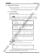

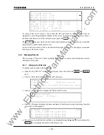

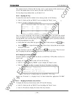

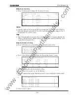

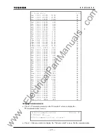

203
6
F
2
S
0
8
5
0
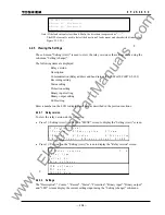
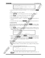
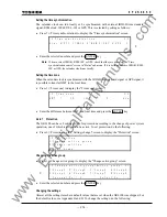
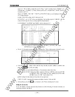
The asterisk on the far left shows that the inner clock is synchronized with the marked source
clock. If the marked source clock is inactive, the inner clock runs locally.
For the setting time synchronization, see Section 4.2.6.6.
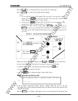
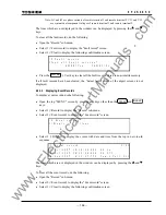
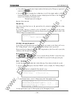
4.2.4.5 Adjusting the Time
To adjust the clock when the internal clock is running locally, do the following:
•
Select 2 (=Status) on the top "MENU" screen to display the "Status" screen.
•
Select 5 (=Clock) to display the setting screen.
/ 2
1 2 / F e b / 1 9 9 8
2 2 : 5 6 : 1 9
[ L o c a l ]
1 / 5
M i n u t e (
0 -
5 9 ) :
4 1
H o u r
(
0 -
2 3 ) :
2 2
D a y
(
1 -
3 1 ) :
1 2
M o n t h (
1 -
1 2 ) :
2
Y e a r
(
1 9 9 0 -
2 0 8 9 ) :
1 9 9 8
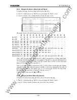
Line 1 shows the current date, time and time synchronization source with which the internal
clock is synchronized. The time can be adjusted only when [Local] is indicated on the top line,
showing that the clock is running locally. When [IRIG] or [RSM] or [IEC] or [GPS] is indicated,
the following adjustment is invalid.
•
Enter a numerical value within the specified range for each item and press the ENTER key.
•
Press
the END key to adjust the internal clock to the set hours without fractions and return
to the previous screen.
If a date which does not exist in the calendar is set and END key is pressed, "Error: Incorrect
date" is displayed on the top line and the adjustment is discarded. Adjust again.
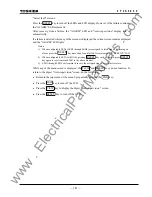
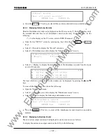
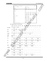
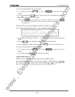
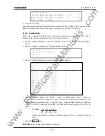
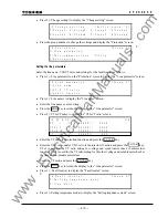
4.2.4.6 Displaying the Terminal Condition
Terminal condition is displayed when the scheme switch [OTD] is "ON" and the out-of-service
logic is used.
To display the terminal condition on the LCD, do the following:
•
Select 2 (= Status) on the top "MENU" screen to display the "Status" screen.
•
Select 6 (= Terminal condition) to display the status of the terminal conditions.
/ 2
u t o f s e r v i c e
T e r m i n a l 1 : I
T e r m i n a l
c o n d i t i o n
n s e r v i c e
T e r m i n a l 2 : O
2 / 2
Note: “Out of service” is displayed when the switch [OTD] ="ON" setting.
Bottom line (Terminal 2:) is displayed only for three-terminal line application ("3TERM"
setting).
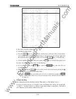
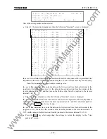
4.2.4.7 Displaying the Direction of Load Current
To display the direction of load current on the LCD, do the following:
•
Select 2 (=Status) on the top "MENU" screen to display the "Status" screen.
•
Select 6 (=Direction) to display the status of the relay elements.
www
. ElectricalPartManuals
. com
Содержание GRL100-701B
Страница 288: ... 287 6 F 2 S 0 8 5 0 Appendix A Block Diagram w w w E l e c t r i c a l P a r t M a n u a l s c o m ...
Страница 290: ... 289 6 F 2 S 0 8 5 0 Appendix B Signal List w w w E l e c t r i c a l P a r t M a n u a l s c o m ...
Страница 324: ... 323 6 F 2 S 0 8 5 0 Appendix C Variable Timer List w w w E l e c t r i c a l P a r t M a n u a l s c o m ...
Страница 329: ... 328 6 F 2 S 0 8 5 0 w w w E l e c t r i c a l P a r t M a n u a l s c o m ...
Страница 339: ... 338 6 F 2 S 0 8 5 0 w w w E l e c t r i c a l P a r t M a n u a l s c o m ...
Страница 348: ... 347 6 F 2 S 0 8 5 0 Appendix G Typical External Connection w w w E l e c t r i c a l P a r t M a n u a l s c o m ...
Страница 351: ... 350 6 F 2 S 0 8 5 0 w w w E l e c t r i c a l P a r t M a n u a l s c o m ...
Страница 381: ... 380 6 F 2 S 0 8 5 0 w w w E l e c t r i c a l P a r t M a n u a l s c o m ...
Страница 388: ... 387 6 F 2 S 0 8 5 0 Appendix J Return Repair Form w w w E l e c t r i c a l P a r t M a n u a l s c o m ...
Страница 394: ... 393 6 F 2 S 0 8 5 0 Appendix K Technical Data w w w E l e c t r i c a l P a r t M a n u a l s c o m ...
Страница 410: ... 409 6 F 2 S 0 8 5 0 Appendix L Symbols Used in Scheme Logic w w w E l e c t r i c a l P a r t M a n u a l s c o m ...
Страница 413: ... 412 6 F 2 S 0 8 5 0 w w w E l e c t r i c a l P a r t M a n u a l s c o m ...
Страница 414: ... 413 6 F 2 S 0 8 5 0 Appendix M Multi phase Autoreclose w w w E l e c t r i c a l P a r t M a n u a l s c o m ...
Страница 417: ... 416 6 F 2 S 0 8 5 0 w w w E l e c t r i c a l P a r t M a n u a l s c o m ...
Страница 418: ... 417 6 F 2 S 0 8 5 0 Appendix N Data Transmission Format w w w E l e c t r i c a l P a r t M a n u a l s c o m ...
Страница 424: ... 423 6 F 2 S 0 8 5 0 Appendix O Example of Setting w w w E l e c t r i c a l P a r t M a n u a l s c o m ...
Страница 440: ... 439 6 F 2 S 0 8 5 0 Appendix Q IEC60870 5 103 Interoperability w w w E l e c t r i c a l P a r t M a n u a l s c o m ...
Страница 453: ... 452 6 F 2 S 0 8 5 0 w w w E l e c t r i c a l P a r t M a n u a l s c o m ...
Страница 454: ... 453 6 F 2 S 0 8 5 0 Appendix R Inverse Time Characteristics w w w E l e c t r i c a l P a r t M a n u a l s c o m ...
Страница 457: ... 456 6 F 2 S 0 8 5 0 w w w E l e c t r i c a l P a r t M a n u a l s c o m ...
Страница 464: ... 463 6 F 2 S 0 8 5 0 Appendix T PLC Setting Sample w w w E l e c t r i c a l P a r t M a n u a l s c o m ...
Страница 468: ... 467 6 F 2 S 0 8 5 0 Appendix U Ordering w w w E l e c t r i c a l P a r t M a n u a l s c o m ...
Страница 473: ...w w w E l e c t r i c a l P a r t M a n u a l s c o m ...