127
6
F
2
S
0
8
5
0
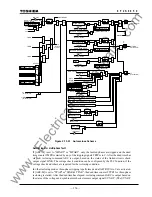
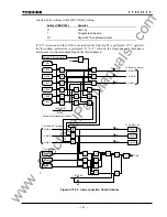
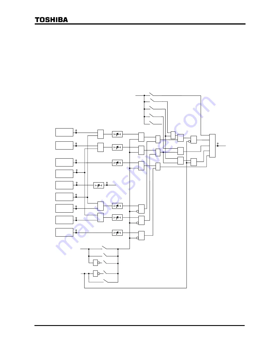
Figure 2.15.2.9 shows the energizing control scheme of the two circuit breakers in the
three-phase autoreclose. OVB and UVB are the overvoltage and undervoltage detectors of
busbar voltage VB in Figure 2.15.2.7. OVL1 and UVL1 are likewise the overvoltage and
undervoltage detectors of line voltage VL1.
OVL2 and UVL2 are likewise the overvoltage and undervoltage detectors of line voltage VL2.
VL2 in the center breaker is equivalent to the busbar voltage VB in the busbar breaker.
SYN1 and SYN2 are the synchronism check elements to check synchronization between the two
sides of the busbar and center breakers, respectively. SYN-OP is a voltage and synchronism
check output.
&
SYN2
UVL2
OVL2
UVL1
OVL1
SYN1
UVB
OVB
[VCHK]
"
LB2
"
"
LB1
"
"
DB
"
"
SYN
"
"
OFF
"
TLBD1
0.01 - 1s
TDBL1
0.01 - 1s
0.01 - 10s
0.01 - 1s
0.01 - 1s
0.01 - 10s
≥
1
≥
1
&
&
&
&
&
&
&
1
&
&
TSYN1
≥
1
≥
1
"
ONE
"
"
L1
"
"
L2
"
"
01
"
"
02
"
[ARC-CB]
ARC-SET
+
+
≥
1
&
&
TLBD2
TDBL2
TSYN2
1
&
&
&
SYN
-OP
57
58
60
61
59
159
62
63
64
T3PLL
0.01 - 1s
3PLL
(Three phase live line)
498
OVL1
(3PH)
78
Note :
[ARC-CB]
is set to "
ONE
" only when the relay is applied to one-breaker system. Trip and reclose
commands are output only for CB1(bus CB).
Figure 2.15.2.9 Energizing Control Scheme for Two Circuit Breakers
www
. ElectricalPartManuals
. com
Содержание GRL100-701B
Страница 288: ... 287 6 F 2 S 0 8 5 0 Appendix A Block Diagram w w w E l e c t r i c a l P a r t M a n u a l s c o m ...
Страница 290: ... 289 6 F 2 S 0 8 5 0 Appendix B Signal List w w w E l e c t r i c a l P a r t M a n u a l s c o m ...
Страница 324: ... 323 6 F 2 S 0 8 5 0 Appendix C Variable Timer List w w w E l e c t r i c a l P a r t M a n u a l s c o m ...
Страница 329: ... 328 6 F 2 S 0 8 5 0 w w w E l e c t r i c a l P a r t M a n u a l s c o m ...
Страница 339: ... 338 6 F 2 S 0 8 5 0 w w w E l e c t r i c a l P a r t M a n u a l s c o m ...
Страница 348: ... 347 6 F 2 S 0 8 5 0 Appendix G Typical External Connection w w w E l e c t r i c a l P a r t M a n u a l s c o m ...
Страница 351: ... 350 6 F 2 S 0 8 5 0 w w w E l e c t r i c a l P a r t M a n u a l s c o m ...
Страница 381: ... 380 6 F 2 S 0 8 5 0 w w w E l e c t r i c a l P a r t M a n u a l s c o m ...
Страница 388: ... 387 6 F 2 S 0 8 5 0 Appendix J Return Repair Form w w w E l e c t r i c a l P a r t M a n u a l s c o m ...
Страница 394: ... 393 6 F 2 S 0 8 5 0 Appendix K Technical Data w w w E l e c t r i c a l P a r t M a n u a l s c o m ...
Страница 410: ... 409 6 F 2 S 0 8 5 0 Appendix L Symbols Used in Scheme Logic w w w E l e c t r i c a l P a r t M a n u a l s c o m ...
Страница 413: ... 412 6 F 2 S 0 8 5 0 w w w E l e c t r i c a l P a r t M a n u a l s c o m ...
Страница 414: ... 413 6 F 2 S 0 8 5 0 Appendix M Multi phase Autoreclose w w w E l e c t r i c a l P a r t M a n u a l s c o m ...
Страница 417: ... 416 6 F 2 S 0 8 5 0 w w w E l e c t r i c a l P a r t M a n u a l s c o m ...
Страница 418: ... 417 6 F 2 S 0 8 5 0 Appendix N Data Transmission Format w w w E l e c t r i c a l P a r t M a n u a l s c o m ...
Страница 424: ... 423 6 F 2 S 0 8 5 0 Appendix O Example of Setting w w w E l e c t r i c a l P a r t M a n u a l s c o m ...
Страница 440: ... 439 6 F 2 S 0 8 5 0 Appendix Q IEC60870 5 103 Interoperability w w w E l e c t r i c a l P a r t M a n u a l s c o m ...
Страница 453: ... 452 6 F 2 S 0 8 5 0 w w w E l e c t r i c a l P a r t M a n u a l s c o m ...
Страница 454: ... 453 6 F 2 S 0 8 5 0 Appendix R Inverse Time Characteristics w w w E l e c t r i c a l P a r t M a n u a l s c o m ...
Страница 457: ... 456 6 F 2 S 0 8 5 0 w w w E l e c t r i c a l P a r t M a n u a l s c o m ...
Страница 464: ... 463 6 F 2 S 0 8 5 0 Appendix T PLC Setting Sample w w w E l e c t r i c a l P a r t M a n u a l s c o m ...
Страница 468: ... 467 6 F 2 S 0 8 5 0 Appendix U Ordering w w w E l e c t r i c a l P a r t M a n u a l s c o m ...
Страница 473: ...w w w E l e c t r i c a l P a r t M a n u a l s c o m ...

