202
6
F
2
S
0
8
5
0
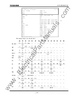
AB BC CA
AB BC CA AB BC CA
UV2
UVS1 UVS2 UVSBLK
— — — — — —
A B C
A B C
A B C
UV3
UVG1 UVG2 UVGBLK
— — — — — —
A B C
A B C
CTF
CTFID CTFUV
CTF
OVG
— — — — — — — —
AB BC CA
A B C
VTF
UVFS UVFG
OVG — — — — — — — —
Autoreclose OVB UVB SYN1 OVL1 UVL1 SYN2 OVL2 UVL2 OVL1
(3PH)
— — — — — —
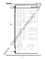
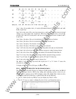
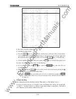
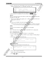
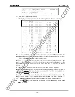
Line 1 shows the operation status of current differential elements for phase faults and earth
faults, respectively.
Line 2 shows the status of the out-of-step protection.
α
and
β
is "1" when the remote terminal
voltage is at
α
-zone and
β
-zone respectively. OST shows the operation status of out-of-step
element. OST1 and OST2 correspond to the out-of-step detection with remote terminal 1 and 2
respectively.
Line 3 shows the status of the overcurrent element for breaker failure protection.
Line 4 shows the status of the overcurrent elements and fail-safe elements.
Line 5 shows the status of the thermal overload element.
Line 6 shows the status of the broken conductor detection element.
Lines 7 and 8 show the status of the distance measuring element for phase and earth faults.
Lines 9 and 10 show the status of the blinder element and power swing blocking element.
Line 11 shows the status of the overcurrent element and directional earth fault element.
Lines 12 to 16 show the status of the overvoltage elements and undervoltage elements.
Lines 17 and 18 show the status of elements used for CTF and VTF detection.
Line 19 shows the status of elements used for autoreclose.
The status of each element is expressed with logical level "1" or "0". Status "1" means the
element is in operation.
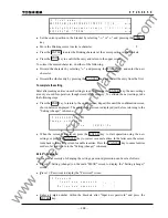
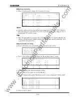
To display all the lines on the LCD, press the and keys.
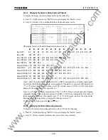
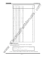
4.2.4.4 Displaying the Status of the Time Synchronization Source
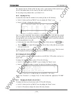
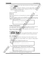
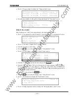
The internal clock of the GRL100 can be synchronized with external clocks such as the IRIG-B
time standard signal clock or RSM (relay setting and monitoring system) clock or by an
IEC60870-5-103 control system or GPS. To display on the LCD whether these clocks are active
or inactive and which clock the relay is synchronized with, do the following:
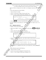
•
Select 2 (=Status) on the top "MENU" screen to display the "Status" screen.
•
Select 4 (=Time sync source) to display the status of time synchronization sources.
/ 2
T i m e s y n c
* I R I G :
A c t i v
h r o n i z a t o n
i
s o u r c e
e
R S M :
a c t i v e
I n
I E C :
a c t i v e
I n
3 /
4
G P S :
a c t i v e
I n
www
. ElectricalPartManuals
. com
Содержание GRL100-701B
Страница 288: ... 287 6 F 2 S 0 8 5 0 Appendix A Block Diagram w w w E l e c t r i c a l P a r t M a n u a l s c o m ...
Страница 290: ... 289 6 F 2 S 0 8 5 0 Appendix B Signal List w w w E l e c t r i c a l P a r t M a n u a l s c o m ...
Страница 324: ... 323 6 F 2 S 0 8 5 0 Appendix C Variable Timer List w w w E l e c t r i c a l P a r t M a n u a l s c o m ...
Страница 329: ... 328 6 F 2 S 0 8 5 0 w w w E l e c t r i c a l P a r t M a n u a l s c o m ...
Страница 339: ... 338 6 F 2 S 0 8 5 0 w w w E l e c t r i c a l P a r t M a n u a l s c o m ...
Страница 348: ... 347 6 F 2 S 0 8 5 0 Appendix G Typical External Connection w w w E l e c t r i c a l P a r t M a n u a l s c o m ...
Страница 351: ... 350 6 F 2 S 0 8 5 0 w w w E l e c t r i c a l P a r t M a n u a l s c o m ...
Страница 381: ... 380 6 F 2 S 0 8 5 0 w w w E l e c t r i c a l P a r t M a n u a l s c o m ...
Страница 388: ... 387 6 F 2 S 0 8 5 0 Appendix J Return Repair Form w w w E l e c t r i c a l P a r t M a n u a l s c o m ...
Страница 394: ... 393 6 F 2 S 0 8 5 0 Appendix K Technical Data w w w E l e c t r i c a l P a r t M a n u a l s c o m ...
Страница 410: ... 409 6 F 2 S 0 8 5 0 Appendix L Symbols Used in Scheme Logic w w w E l e c t r i c a l P a r t M a n u a l s c o m ...
Страница 413: ... 412 6 F 2 S 0 8 5 0 w w w E l e c t r i c a l P a r t M a n u a l s c o m ...
Страница 414: ... 413 6 F 2 S 0 8 5 0 Appendix M Multi phase Autoreclose w w w E l e c t r i c a l P a r t M a n u a l s c o m ...
Страница 417: ... 416 6 F 2 S 0 8 5 0 w w w E l e c t r i c a l P a r t M a n u a l s c o m ...
Страница 418: ... 417 6 F 2 S 0 8 5 0 Appendix N Data Transmission Format w w w E l e c t r i c a l P a r t M a n u a l s c o m ...
Страница 424: ... 423 6 F 2 S 0 8 5 0 Appendix O Example of Setting w w w E l e c t r i c a l P a r t M a n u a l s c o m ...
Страница 440: ... 439 6 F 2 S 0 8 5 0 Appendix Q IEC60870 5 103 Interoperability w w w E l e c t r i c a l P a r t M a n u a l s c o m ...
Страница 453: ... 452 6 F 2 S 0 8 5 0 w w w E l e c t r i c a l P a r t M a n u a l s c o m ...
Страница 454: ... 453 6 F 2 S 0 8 5 0 Appendix R Inverse Time Characteristics w w w E l e c t r i c a l P a r t M a n u a l s c o m ...
Страница 457: ... 456 6 F 2 S 0 8 5 0 w w w E l e c t r i c a l P a r t M a n u a l s c o m ...
Страница 464: ... 463 6 F 2 S 0 8 5 0 Appendix T PLC Setting Sample w w w E l e c t r i c a l P a r t M a n u a l s c o m ...
Страница 468: ... 467 6 F 2 S 0 8 5 0 Appendix U Ordering w w w E l e c t r i c a l P a r t M a n u a l s c o m ...
Страница 473: ...w w w E l e c t r i c a l P a r t M a n u a l s c o m ...

