14
6
F
2
S
0
8
5
0
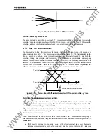
restraint. For details of the characteristic, see Section 2.16.
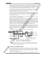
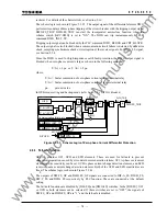
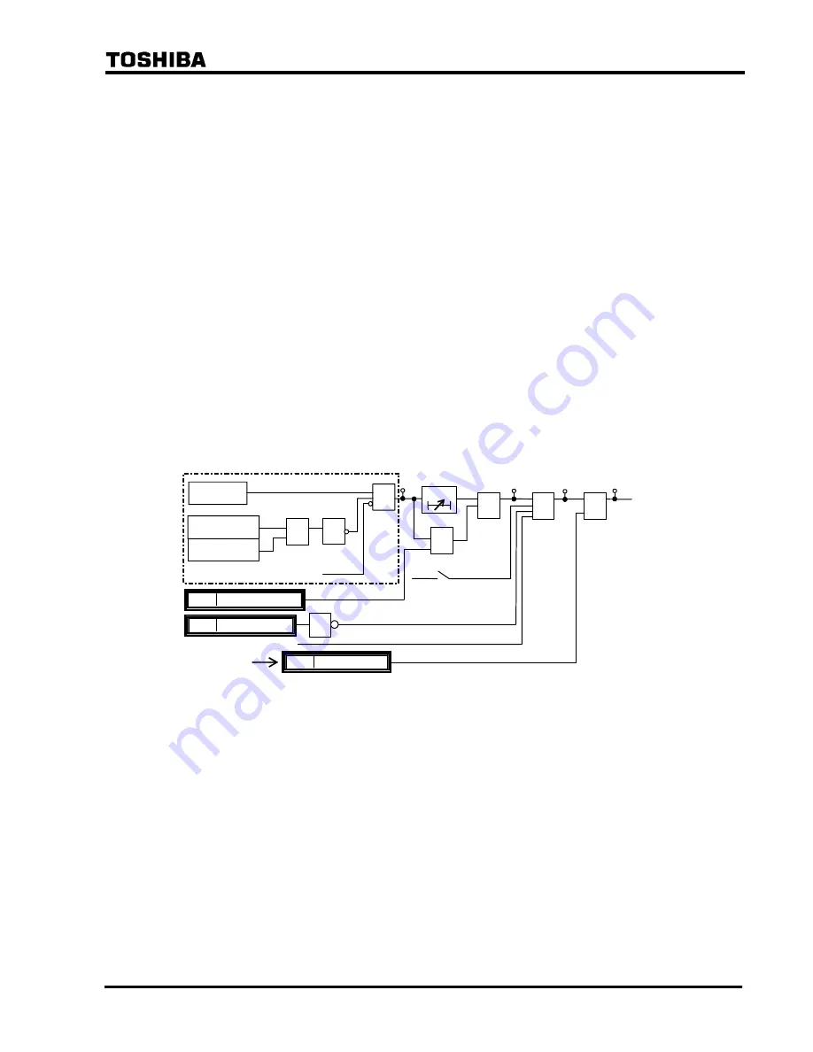
The scheme logic is shown in Figure 2.2.3.1. The output signal of the differential element DIFG
performs time-delayed three-phase tripping of the circuit breaker with the tripping output signal
DIFG.FS_TRIP. DIFG.FS_TRIP can start the incorporated autoreclose function when the
scheme switch [ARC-DIFG] is set to "ON". The DIFG can trip instantaneously by PLC
command DIFG_INST_TP.
Tripping output signal can be blocked by the PLC command DIFG_BLOCK and CRT_BLOCK.
The output signal is also blocked when a communication circuit failure is detected by data error
check, sampling synchronism check or interruption of the receive signals. For DIFG_FS signal,
see Section 2.2.4.
Since the DIFG is used for high-impedance earth fault protection, the DIFG output signal is
blocked when zero-phase current is large as shown in the following equation:
Σ
I
01
≥
2 pu or
Σ
I
02
≥
2 pu
where,
Σ
I
01
: Scalar summation of zero-phase current at local terminal relay
Σ
I
02
: Scalar summation of zero-phase current at remote terminal relay
pu: per unit value
In GPS-mode setting and backup mode (refer to 2.2.7.2), DIFG is blocked.
DIFG
DIFG.FS_TRIP
"ON"
&
1
Σ
I
01
≥
2PU
Σ
I
02
≥
2PU
≥
1
Communication failure, etc.
1
DIFG_BLOCK
1586
85
44
DIFG_FS
1619
&
404
43C ON
86
DIFG_TRIP
DIFGFS
DIFG_INST_TP
1632
≥
1
&
+
[DIFG]
t 0
TDIFG
0.0-10.0s
&
Figure 2.2.3.1 Scheme Logic of Zero-phase Current Differential Protection
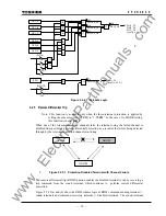
2.2.4 Fail-safe
Function
GRL100 provides OC1, OCD and EFD elements. These are used for fail-safe to prevent
unnecessary operation caused by error data in communication failure. OC1 is phase overcurrent
element and its sensitivity can be set. OCD is phase current change detection element, and EFD
is zero-sequence current change detection element. Both of the OCD and EFD sensitivities are
fixed. The scheme logic is shown in Figure 2.2.4.1.
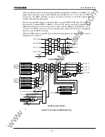
The outputs of DIF.FS_OP and DIFG.FS_OP signals are connected to DIF-A_FS, DIF-B_FS,
DIF-C_FS and DIFG_FS respectively by PLC function. These are connected at the default
setting.
The fail-safe functions are disabled by [DIF-FS] and [DIFG-FS] switches. In the [DIF-FS], OC1
or OCD or both elements can be selected. If these switches are set to “OFF”, the signals of
DIF.FS_OP and DIFG.FS_OP are “1” and the fail-safe is disabled.
www
. ElectricalPartManuals
. com
Содержание GRL100-701B
Страница 288: ... 287 6 F 2 S 0 8 5 0 Appendix A Block Diagram w w w E l e c t r i c a l P a r t M a n u a l s c o m ...
Страница 290: ... 289 6 F 2 S 0 8 5 0 Appendix B Signal List w w w E l e c t r i c a l P a r t M a n u a l s c o m ...
Страница 324: ... 323 6 F 2 S 0 8 5 0 Appendix C Variable Timer List w w w E l e c t r i c a l P a r t M a n u a l s c o m ...
Страница 329: ... 328 6 F 2 S 0 8 5 0 w w w E l e c t r i c a l P a r t M a n u a l s c o m ...
Страница 339: ... 338 6 F 2 S 0 8 5 0 w w w E l e c t r i c a l P a r t M a n u a l s c o m ...
Страница 348: ... 347 6 F 2 S 0 8 5 0 Appendix G Typical External Connection w w w E l e c t r i c a l P a r t M a n u a l s c o m ...
Страница 351: ... 350 6 F 2 S 0 8 5 0 w w w E l e c t r i c a l P a r t M a n u a l s c o m ...
Страница 381: ... 380 6 F 2 S 0 8 5 0 w w w E l e c t r i c a l P a r t M a n u a l s c o m ...
Страница 388: ... 387 6 F 2 S 0 8 5 0 Appendix J Return Repair Form w w w E l e c t r i c a l P a r t M a n u a l s c o m ...
Страница 394: ... 393 6 F 2 S 0 8 5 0 Appendix K Technical Data w w w E l e c t r i c a l P a r t M a n u a l s c o m ...
Страница 410: ... 409 6 F 2 S 0 8 5 0 Appendix L Symbols Used in Scheme Logic w w w E l e c t r i c a l P a r t M a n u a l s c o m ...
Страница 413: ... 412 6 F 2 S 0 8 5 0 w w w E l e c t r i c a l P a r t M a n u a l s c o m ...
Страница 414: ... 413 6 F 2 S 0 8 5 0 Appendix M Multi phase Autoreclose w w w E l e c t r i c a l P a r t M a n u a l s c o m ...
Страница 417: ... 416 6 F 2 S 0 8 5 0 w w w E l e c t r i c a l P a r t M a n u a l s c o m ...
Страница 418: ... 417 6 F 2 S 0 8 5 0 Appendix N Data Transmission Format w w w E l e c t r i c a l P a r t M a n u a l s c o m ...
Страница 424: ... 423 6 F 2 S 0 8 5 0 Appendix O Example of Setting w w w E l e c t r i c a l P a r t M a n u a l s c o m ...
Страница 440: ... 439 6 F 2 S 0 8 5 0 Appendix Q IEC60870 5 103 Interoperability w w w E l e c t r i c a l P a r t M a n u a l s c o m ...
Страница 453: ... 452 6 F 2 S 0 8 5 0 w w w E l e c t r i c a l P a r t M a n u a l s c o m ...
Страница 454: ... 453 6 F 2 S 0 8 5 0 Appendix R Inverse Time Characteristics w w w E l e c t r i c a l P a r t M a n u a l s c o m ...
Страница 457: ... 456 6 F 2 S 0 8 5 0 w w w E l e c t r i c a l P a r t M a n u a l s c o m ...
Страница 464: ... 463 6 F 2 S 0 8 5 0 Appendix T PLC Setting Sample w w w E l e c t r i c a l P a r t M a n u a l s c o m ...
Страница 468: ... 467 6 F 2 S 0 8 5 0 Appendix U Ordering w w w E l e c t r i c a l P a r t M a n u a l s c o m ...
Страница 473: ...w w w E l e c t r i c a l P a r t M a n u a l s c o m ...


