


– 5 –
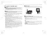
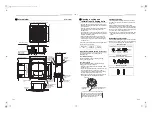
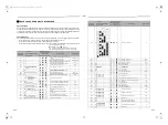
External view
Unit: in (mm)
23.4” to 26”(595 to 660) Ceiling open dimension
23
.4
” t
o
26”
(5
95
t
o
66
0)
C
eil
in
g op
en
d
imen
si
on
5.
9”
(1
49
)
22
.6
”(
57
5) U
n
it ex
te
rn
al
di
me
ns
io
n
Bottom face of ceiling
27.6”(700) Panel external dimension
Electrical control
box
Bottom face
of ceiling
23.4” to 26”(595 to 660) Ceiling open dimension
20.7”(525) Hanging bolt pitch
12.6”(320.5)
7.
0”
(17
7
)
20
.1
”(
51
0)
H
a
ng
in
g bol
t pi
tc
h
23
.4
” to
2
6”
(595
to
66
0)
C
eil
in
g ope
n di
mensi
on
27.
6”
(7
00
) Pane
l e
xte
rn
al
di
me
ns
io
n
22.6”(575) Unit external dimension
Refrigerant
pipe (Liquid)
Ø1/4”(6.4)
Refrigerant pipe (Gas)
AP015, AP018:
Ø1/2”(12.7)
AP007 to AP012:
Ø3/8”(9.5)
Drain pipe
connecting port
Hanging bolt
3/8”(10) local
arrange
10.6”(268)
1.1”(27)
8.7”(220.5)
1.
7”
(4
2)
3.
8”
(9
7.
5)
7.5”(190.5)
2.1”
(53)
Wiring connection
port (for control
wiring)
Ceiling panel
Bottom face
of ceiling
Hole for power
supply cable
Knockout for Auxiliary
fresh air flange
For Ø 3.9”(100)
Bottom face of ceiling
2.5”
(64
)
1.1”
(29
)
5.5”(142) 2.5”
(64)
14.5”(368.5)
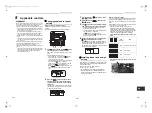
Opening a ceiling and
installation of hanging bolts
• Consider the piping / wiring after the unit is hung to
determine the location of the indoor unit installation
and orientation.
• After the location of the indoor unit installation has
been determined, open the ceiling and install
hanging bolts.
• The dimensions of the ceiling opening and hanging
bolt pitches are given in the outline drawing and the
attached installation pattern.
• When a ceiling already exists, lay the drain pipe,
refrigerant pipe, control wires, and remote control
wires to their connection locations before hanging
the indoor unit.
Procure hanging bolts and nuts for installing the indoor
unit (these are not supplied).
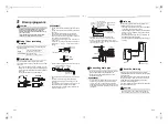
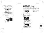
Using the installation pattern (accessory)
The installation pattern is provided inside the
packaging cap.
<For existing ceiling>
Use the installation pattern positioning a ceiling
opening and hanging bolts.
<For new ceiling>
Use the installation pattern to position the ceiling
opening when a ceiling is hanged.
• After the hanging bolts have been installed, install
the indoor unit.
• To use the supplied pattern attach it to the indoor unit
using the supplied fixing screws (0.2”(5 mm) ×
0.6”(16 mm) 4 pcs.). (Screw pattern to the ceiling
panel hanging brackets of the indoor unit)
• Before hanging a ceiling, open the ceiling along the
outside dimensions of the installation pattern.
Treatment of ceiling
The ceiling differs according to structure of building.
For details, consult your constructor or interior finish
contractor.
In the process after the ceiling board has been
removed, it is important to reinforce ceiling foundation
(frame) and to keep horizontal level of installed ceiling
correctly in order to prevent vibration of ceiling board.
1. Cut and remove the ceiling foundation.
2. Reinforce the cut surface of ceiling foundation, and
add ceiling foundation for fixing the end of ceiling
board.
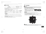
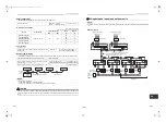
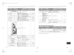
Installation of hanging bolt
Use 3/8” (M10) hanging bolts (4 pcs, locally procured).
Matching to the existing structure, set pitch according
to size in the unit external view as shown below.
Hanging bolt
3/8” (M10)
4 pieces
Nut
3/8” (M10)
12 pieces
Indoor unit
Installation pattern
(Attached)
0.2” (5 mm) × 0.6” (16 mm) screws (Attached)
These screws are exclusive to the installation
pattern. When installing the ceiling panel, the
other exclusive screws attached to the ceiling
panel (sold separately) are used.
Cut off the installation pattern
along slit of the main unit.
New concrete slab
Install the bolts with insert brackets or anchor bolts.
Steel flame structure
Use existing angles or install new support angles.
Existing concrete slab
Use a hole-in anchors, hole-in plugs, or a hole-in bolts.
Rubber
Anchor bolt
(Blade type
bracket)
(Slide type
bracket)
(Pipe hanging
anchor bolt)
Hanging bolt
Hanging bolt Support angle
9-EN
10-EN
+00EH99876101-2_00Ta.book Page 5 Monday, September 1, 2014 10:15 AM


