


– 15 –
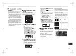
Check codes and parts to be checked
Check method
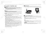
On the remote control (Wired remote control, Central control remote control) and the interface P.C. board of the
outdoor unit (I/F), a check display LCD (Remote control) or 7-segment display (on the outdoor interface P.C. board)
to display the operation is provided. Therefore the operation status can be known. With this self-diagnosis function,
a trouble or position with error of the air conditioner can be found as shown in the table below.
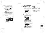
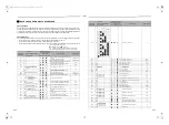
Check code list
The following list shows each check code. Find the check contents from the list according to part to be checked.
• To check from indoor remote control: See “Wired remote control display” in the list.
• To check from outdoor unit: See “Outdoor 7-segment display” in the list.
• To check from indoor unit with a wireless remote control: See “Sensor block display of receiving unit” in the list.
IPDU : Intelligent Power Drive Unit
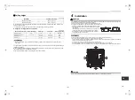
: Lighting,
: Flashing,
: Goes off
ALT. : Flashing is alternately when there are two flashing LED.
SIM : Simultaneous flashing when there are two flashing LED.
Check code
Wireless remote control
Check code name
Judging device
Wired remote
control display
Outdoor 7-segment display
Sensor block display of
receiving unit
Auxiliary code
Operation Timer Ready Flash
E01
—
—
Communication error between indoor and remote
control
(Detected at remote control side)
Remote control
E02
—
—
Remote control transmission error
Remote control
E03
—
—
Communication error between indoor and remote
control (Detected at indoor side)
Indoor
E04
—
—
Communication circuit error between indoor/
outdoor (Detected at indoor side)
Indoor
E06
E06
No. of indoor units in which
sensor has been normally
received
Decrease of No. of indoor units
I/F
—
E07
—
Communication circuit error between indoor/
outdoor (Detected at outdoor side)
I/F
E08
E08 Duplicated indoor addresses
Duplicated indoor addresses
Indoor / I/F
E09
—
—
Duplicated header remote controls
Remote control
E10
—
—
Communication error between indoor MCU
Indoor
E12
E12
01: Indoor/Outdoor
communication
02: Communication between
outdoor units
Automatic address start error
I/F
E15
E15
—
Indoor is nothing during automatic addressing
I/F
E16
E16 00: Capacity over
01 ~:No. of connected units
Capacity over / No. of connected indoor units
I/F
E18
—
—
Communication error between indoor units
Indoor
E19
E19 00: Header is nothing
02: Two or more header units
Outdoor header units quantity error
I/F
E20
E20
01: Outdoor of other line
connected
02: Indoor of other line connected
Other line connected during automatic
address
I/F
E23
E23
—
Sending error in communication between
outdoor units
I/F
E25
E25
—
Duplicated follower outdoor addresses
I/F
E26
E26 No. of outdoor units which
received signal normally
Decrease of No. of connected outdoor units
I/F
E28
E28 Detected outdoor unit number
Follower outdoor unit error
I/F
E31
E31
IPDU communication error
I/F
F01
—
—
ALT Indoor TCJ sensor error
Indoor
F02
—
—
ALT Indoor TC2 sensor error
Indoor
F03
—
—
ALT Indoor TC1 sensor error
Indoor
F04
F04
—
ALT TD1 sensor error
I/F
F05
F05
—
ALT TD2 sensor error
I/F
F06
F06 TE1 sensor
TE2 sensor
ALT TE1 sensor error
TE2 sensor error
I/F
F07
F07
—
ALT TL sensor error
I/F
F08
F08
—
ALT TO sensor error
I/F
F10
—
—
ALT Indoor TA sensor error
Indoor
F12
F12
—
ALT TS1 sensor error
I/F
F13
F13
01: Comp. 1 side
02: Comp. 2 side
03: Comp. 3 side
ALT TH sensor error
IPDU
F15
F15
—
ALT Outdoor temp. sensor miswiring (TE1, TL)
I/F
F16
F16
—
ALT Outdoor pressure sensor miswiring (Pd, Ps)
I/F
F22
F22
—
ALT TD3 error
I/F
F23
F23
—
ALT Ps sensor error
I/F
F24
F24
—
ALT Pd sensor error
I/F
F29
—
—
SIM Indoor other error
Indoor
F31
F31
—
SIM Indoor EEPROM error
I/F
H01
H01
01: Comp. 1 side
02: Comp. 2 side
03: Comp. 3 side
Compressor break down
IPDU
H02
H02
01: Comp. 1 side
02: Comp. 2 side
03: Comp. 3 side
Compressor trouble (lock)
IPDU
H03
H03
01: Comp. 1 side
02: Comp. 2 side
03: Comp. 3 side
Current detect circuit system error
IPDU
H05
H05
—
TD1 miswiring
I/F
H06
H06
—
Low pressure protective operation
I/F
H07
H07
—
Oil level down detective protection
I/F
H08
H08
01: TK1 sensor error
02: TK2 sensor error
03: TK3 sensor error
04: TK4 sensor error
Oil level detective temp sensor error
I/F
H15
H15
—
TD2 miswiring
I/F
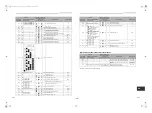
Check code
Wireless remote control
Check code name
Judging device
Wired remote
control display
Outdoor 7-segment display
Sensor block display of
receiving unit
Auxiliary code
Operation Timer Ready Flash
A3-IPDU
Fan
IPDU
1
2
3
01
02
03
04
05
06
07
08
09
0A
0B
0C
0D
0E
0F
: IPDU error
29-EN
30-EN
+00EH99876101-2_00Ta.book Page 15 Monday, September 1, 2014 10:15 AM


