


– 11 –
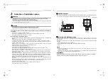
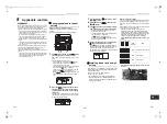
Wire connection
REQUIREMENT
• Connect the wires matching the terminal numbers. Incorrect connection causes a trouble.
• Route the wire through the wire connection port of the indoor unit.
• The low-voltage circuit is provided for the control wire and remote control wire. (Do not connect the high-voltage
circuit.)
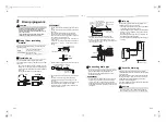
• Remove the cover of the electrical control box by removing the mounting screws (3 positions) and push the
hooking section. (The cover of the electrical control box remains hanged to the hinge.)
• Remove the wire cover by removing the mounting screws. (1 position)
• Remove the conduit plate B by removing the mounting screws. (1 position)
• Attach the conduit pipe to the conduit plate A with a lock nut.
• Tighten the screws on the terminal block and secure the wires with cord clamp fitted to the electrical control box.
(Do not apply tension to the connecting section of the terminal block.)
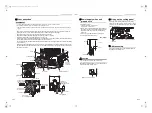
• Use the supplied heat insulation for the sealing of the control wire connecting port. (Otherwise dew condensation
may be caused.)
• Mount the conduit plate B, the wire cover and the cover of the electrical control box ensuring the wires are not
pinched. (Mount the conduit plate B, the wire cover and the cover after the ceiling panel has been wired to the
electrical control box.)
U
1
U
2
A B
L
1
L
2
L
1
L
2
Screw
Cover of
electrical
control box
Electrical control box
Screw
Wire cover
Conduit plate B
Screw
Conduit plate A
Screw
Lock nut
Conduit plate
A
Conduit pipe
Adhered surface
Slit section
Heat insulator A
Ground screw
for shielded wire
Power supply
terminal block
Control wire
(2-core shielded wire)
Control wire
connecting port
Control wire /
Remote control
terminal block
Cord clamp
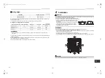
Ground screw
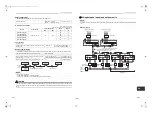
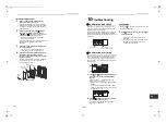
Power supply wires and
ground wire
1. Strip the wire ends.
Power supply wire: 0.4” (10 mm)
Ground wire: 0.8” (20 mm)
2. Match the wire colors with the terminal numbers on
the indoor units’ and circuit breakers’ terminal blocks
and firmly screw the wires to the corresponding
terminals.
3. Secure the ground wire with the ground screw.
4. Fix the wires with a cord clamp.
Unit: in (mm)
CAUTION
Firmly tighten the screws of the terminal block.
Keep the wire length as shown in figure below when it
is connected to the terminal block.
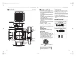
Wiring on the ceiling panel
According to the Installation Manual of the ceiling
panel, connect the connector (2P: Red) of the ceiling
panel to the connector (5P: White) on P.C. board of the
electrical control box.
Address setup
Set up the addresses as per the Installation Manual
supplied with the outdoor unit.
L
1
L
2
0.8” (20)
1.2” (30)
0.4” (10)
Ground wire
0.
08
” (2
) or
le
ss
Power supply wires and control
wire
Cord Clamp
5P connector (White)
Wire from ceiling panel
21-EN
22-EN
+00EH99876101-2_00Ta.book Page 11 Monday, September 1, 2014 10:15 AM


