Mower Spindle Removal (continued)
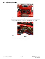
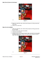
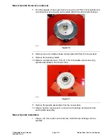
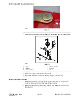
7. From the topside of the mower deck, remove the (0.750-16 inch) spindle lock
nut and washer securing the each spindle shaft to the drive blade sheaves.
g344425
Figure 86
8. Remove each drive blade sheave and spindle shaft from the mower deck.
9. Remove the bearing shields.
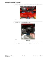
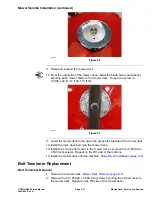
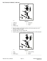
10. Remove and discard the 6 (5.16-18 x 7/8 inch) taptite screws securing
spindle assemblies to the mower deck.
g344426
Figure 87
11. Remove the spindle assemblies from the mower deck.
12. Using a hammer and a punch, remove the 2 bearings and spacers from
each spindle assembly.
Mower Spindle Installation
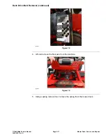
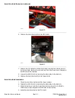
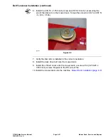
1. Using a (32 mm) socket and a hammer, install the top bearings into the
spindles.
TITAN® Max Service Manual
Page 6–15
Mower Deck: Service and Repairs
3442-428 Rev A
Содержание TITAN
Страница 2: ...Revision History Revision History Page 2 TITAN Max Service Manual 3442 428 Rev A ...
Страница 6: ...Preface Page 6 TITAN Max Service Manual 3442 428 Rev A ...
Страница 20: ...Specifications and Maintenance Torque Specifications Page 2 10 TITAN Max Service Manual 3442 428 Rev A ...
Страница 26: ...Troubleshooting General Troubleshooting Page 3 6 TITAN Max Service Manual 3442 428 Rev A ...
Страница 36: ...Engine Service and Repairs Page 4 10 TITAN Max Service Manual 3442 428 Rev A ...
Страница 70: ...Chassis Service and Repairs Page 5 34 TITAN Max Service Manual 3442 428 Rev A ...
Страница 92: ...Mower Deck Service and Repairs Page 6 22 TITAN Max Service Manual 3442 428 Rev A ...
Страница 118: ...Electrical System Service and Repairs Page 8 18 TITAN Max Service Manual 3442 428 Rev A ...
Страница 121: ... Drawing Rev A Sheet 1 3442 428 Rev A Page A 3 Kohler Engine Electrical Schematic g350654 ...

